We've had pretty constant rain for the last several days so I haven't been able to do much. It looks like it should clear up by the weekend.
Thanks everyone for the kind words, nice to see a couple of others chiming in too.
Nick -
Most of the flanges I've put back together were bare metal after I cleaned them up. I was thinking that if they were closer there was more chance for them to rust together or cause galvanic corrosion. I think the silicone will stop most of it but you're right, it might be a good idea to paint them too.
I think whatever method I use I'll still get a bit of carbon or grit or something in the bearings, so I plan to give it another waterblast and then clean out the bearings with water displacement lube before filling it with oil. At least there's a bit of oil circulation and a filter so hopefully most of the loose particles should be caught.
The extra lever appears to have two positions. I really don't know what those could be. It doesn't control the centre PTO as that's fixed on the same shaft as the rear PTO. I may just end up disassembling the trans to take a look if nobody else knows.
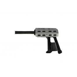
That needle scaler looks like a useful tool. I think there may be an air compressor I could use but I can't justify buying a scaler at the moment. Hammer and a screwdriver gets the job done (slowly). I do have access to some angle grinders and a good range of wire brushes.
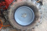
Good work on those wheels, they look a lot worse than mine although it doesn't look like those have holes in them.
I think what happened to the coupling is that the rubber is supposed to be thicker. But it's been compressed and expanded outwards so it's now thinner. I'm not sure I can obtain a new rubber peice right now so I'll just tighten it up. But it might result in a little less efficiency in decoupling engine pulsing from the transmission.
Clementine -
Thanks for sharing your experiences. I might do something similar for the muffler. Do you think 90W (or 80W like the manual) oil is a better choice than UTF for the front axle and steering box etc? With that gasket tip, is that just meant to score it or punch the hole right out? I did find that there are hollow punches which can be used to make the bolt holes - that was the part which seemed like it would be difficult to me when making a gasket by hand.
I have read about the reverse PTO. It's not a big issue to me as I don't expect to use it much. We do have a tiny flail mower that was used for it, and possibly a rotary tiller/cultivator as well. Both probably in very bad condition.
There is a
PTO reverser I found available on Alibaba. The price doesn't seem to bad. The company also seems to make or sell many other reproductions of original Kubota (and other Japanese tractor) parts, even a copy of the original 3 point hitch setup.
Edinottawa -
I've read a bit about the "grey market" models and seen some pictures of the middle mount mower. As I understand it the grey market models are parallel imported while the US model was imported and sold by dealers. All of the Kubota B6000 tractors I've seen in NZ and several other countries seem to be the original Japanese model. Not sure if they were imported by dealers here but it doesn't really seem right to call them grey market models.
This tractor actually doesn't have a front splined PTO - though this could probably be added by bolting an adapter flange on to the the three threaded holes on the main engine pulley. And there is definitely a splined PTO available in the middle that runs off the same shaft as the rear PTO. You can see it in
this photo with the clear tube that was on it. I think it's the same spline as the rear PTO. I wonder if this is one of the differences between the Japanese and USA versions?
I still don't own the tractor. I'm sure others will be wanting to use it once it's running but as long as it stays on the farm that's cool with me. Otherwise if I can't keep it here I'd take off some of the new parts I bought to resell them and replace with the originals. Then it won't be so attractive any more. It's still worth it for the experience as I'm learning a lot.
---------------------
Apart from the mystery lever I still have another question that needs answering, and that's about the wheel size. I've broken that out into another thread:
I have a Kubota B6000 4WD that has 4-10 front tyres and 7-14 rear tyres. I'm not sure if they're original. Tractordata.com says the B6000 4WD has 6-12 and 7-16 tyres. it also says the B5000 has 4-10 and 7-14 tyres. I wonder if these rims and tyres could be from a B5000? A lot of the B6000...

www.orangetractortalks.com
I also want some more info about the two way cock for aux hydraulics connection. I've made a thread here:
The Kubota B6000 is capable of controlling auxiliary single action hydraulics with the same lever used for the rear lift arms. This seems like a pretty clean and simple way of adding aux hydraulics to me. Using an integration block or plumbing more valves inline might be more versatile but also...
www.orangetractortalks.com
I removed the glow plugs (which both seemed ok), did a lot of research on them and made yet another thread:
These are the original glow plugs from a B6000. They say Y-107-1, 46 and 10.5V on both of them. They measure 971mΩ and 989mΩ which would make for 10.8 or 10.6A current draw respectively at 10.5V. There are a couple other threads of interest: On this thread there are a few people saying they...
www.orangetractortalks.com
Now back to my log. Here's what I did in the two or three days before it started raining.
I removed the seal on the transmission main shaft by gripping it with pliers and rotating it until I could get it out. It's a metal flanged seal which reads NOK TC5 17 32 9 1.4. It's 17x32x9mm. I'm not sure I can find an exact replacement with a flange so I may just put this one back.
View attachment 71477
View attachment 71476
I removed both rear wheels. The big bolts on the hub (just one on each hub on my version) that screw against the axle were very hard to remove. I used a lot of penetrating oil and an impact wrench (tightening then loosening) and I managed to get the right side off. The left side was still stubborn. I tried using my gear puller but it was a bit small and I just sheared a bolt off. After a while I managed to knock it in with a hammer which then allowed me to use the impact wrench to remove the large bolt. Then I slowly knocked the hub off the axle.
View attachment 71478
View attachment 71479
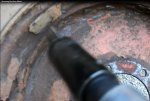
Both rear wheels had a bit of rust around the valves. But not too bad.
View attachment 71481
View attachment 71480
I made a cover for the air intake and hydraulic pump area out of wood. And I temporarily re-attached the exhaust manifold.
View attachment 71483
View attachment 71482


.jpg")


