Overview:
I was looking around and did not see much information on repairing the 3 pt lift cylinder, so I figured I would toss some pictures and parts from my replacement for others to look at, and maybe I can learn something from y'all about the parts I was not super satisfied with.
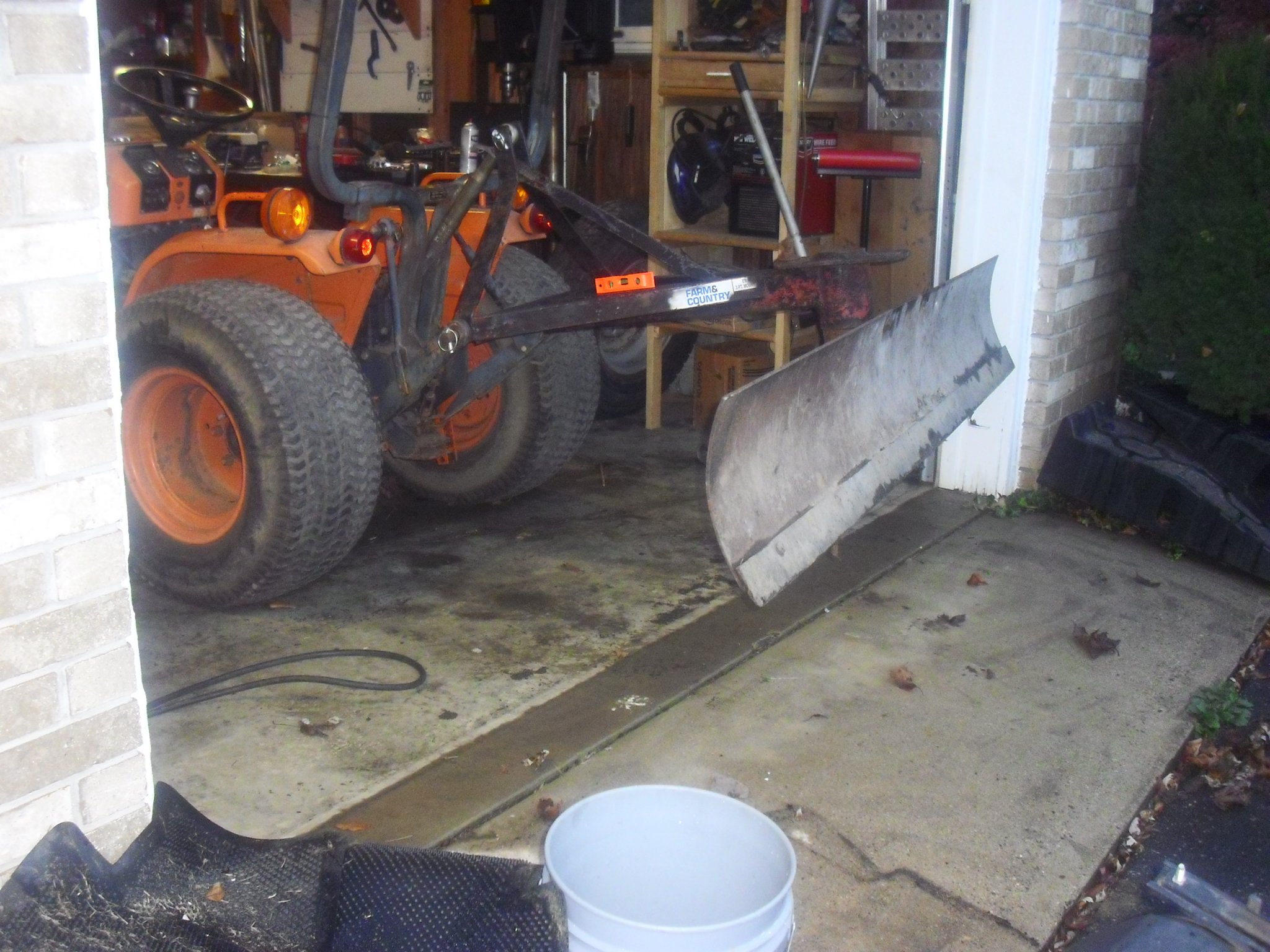
The Problem: The 3 point hitch sinks/wont hold an implement in the air, mine was dropping my blade 32 inches to the ground in less than 2 min.
The Solution: New seals in the lift cylinder. as of today, my blade has dropped 9 inches in 48 hours, still 23 inches from the ground.
Parts Required:
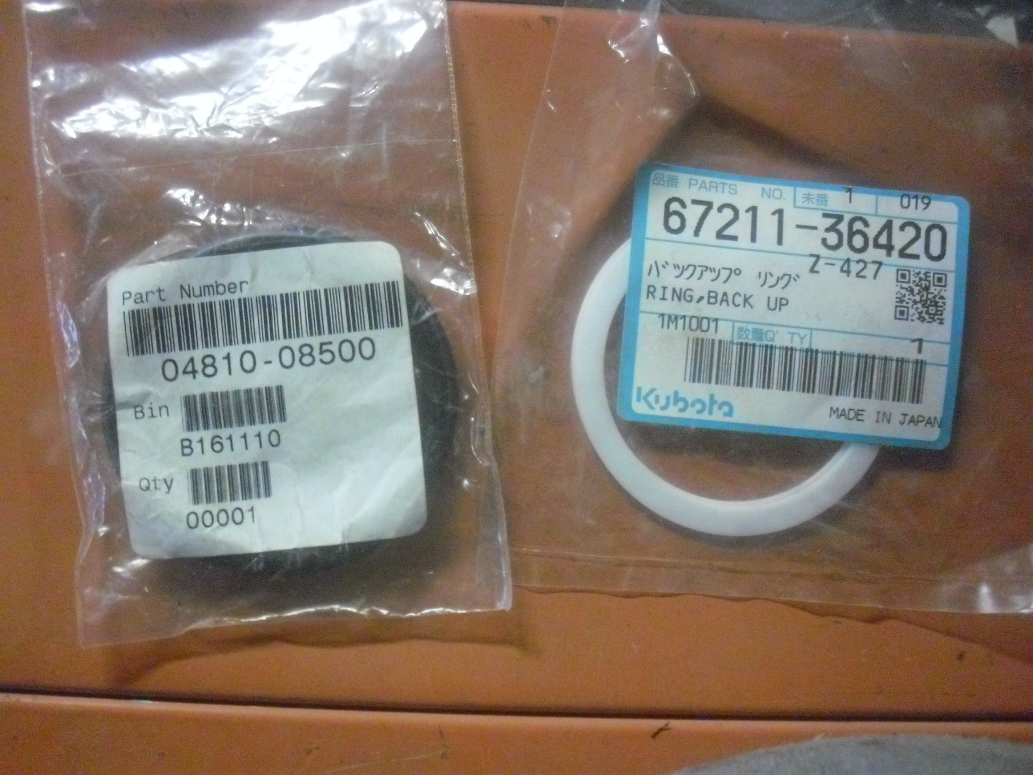
When I called the dealer, they sold me 2 parts (about $12 total).
NOTE: All parts listed are for the B7200 HST 2WD, check parts diagram for your machine! I personally like using Messicks for diagrams and parts.
The Piston O-Ring: 04810-08500
Back up Ring: 67211-36420
I assumed (incorrectly) that the cover was just a gasket, and I would replace it with RTV. This is wrong, I should have looked at the diagram myself. There are 2 more O-rings for the cover, I recommend replacing these as well, it is only $4 more. Thankfully mine were good enough and were able to be reused.
Cover o-ring, for cylinder: 04810-50550
Cover o-ring, to control valve: 04811-00080
The Repair Process:
Now, I am no expert mechanic, and I am certainly not an equipment specialist, but can find my way around the garage well enough. The entire process took about 3 hours, but could conceivably be done in 2 if you are not taking pictures and have some idea what you are doing. That said, hopefully more people will add some tips, tricks and process improvements in the comments, I would love to hear what you would do differently!
Step 1: Remove the seat
The seat is held on with 4 bolts. The ones in the front are 14mm and are easily removed with a socket and 6 inch extension, the ones in the rear are 12mm and were best removed with a ratchet wrench, but a socket could be used if you remove the cross member. I chose to remove it at the brackets so that I could have more room to work, and it eliminates the risk of messing up the rail alignment.
12mm bolt heads (rear) 14mm bolt heads (front)
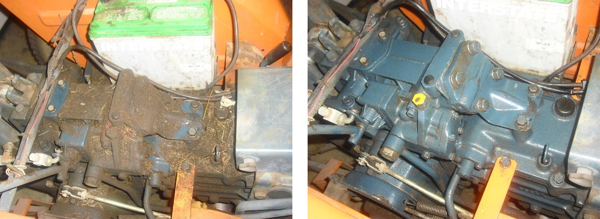
Step 2: Clean it up
Do yourself a favor and clean the area. Especially if yours looks like mine, you don't want that getting inside, and it will let more heat off anyway (a good thing).
All I used was a nylon brush and compressed air, roughly 115 psi and only took 10 min.
NOTE: I suggest replacing the bolts prior to cleaning, this will keep the holes from getting dirt in them
NOTE: The paint is NOT resistant to harsh chemicals such as break cleaner, it will take the paint with it.
Before After
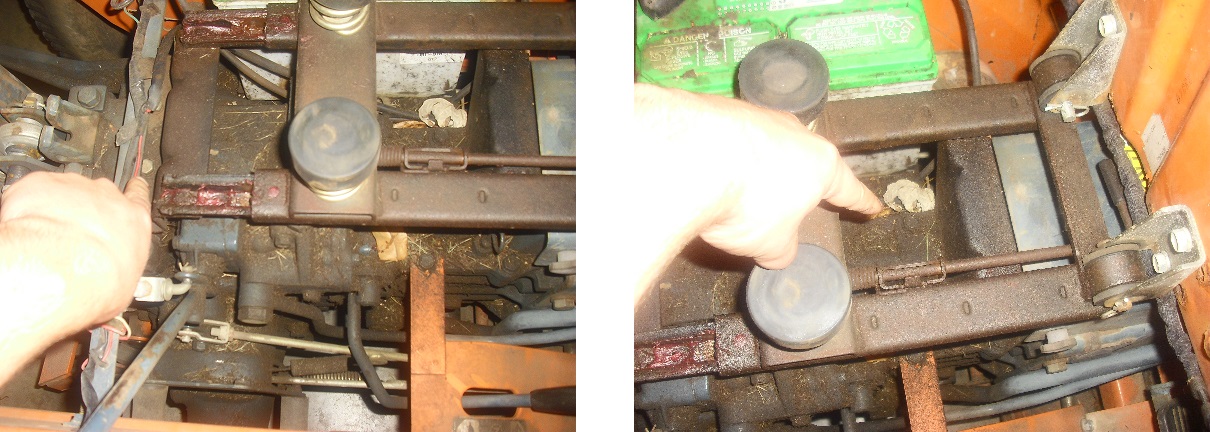
Step 2: Remove the piston cover
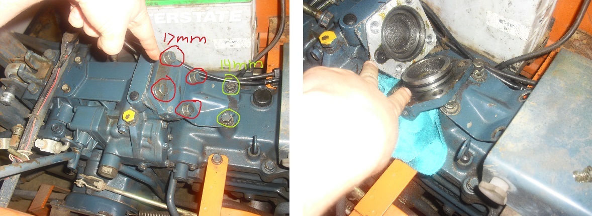
You will need to remove 6 bolts in total, 4 x 17mm for the cover and 2 x 14mm for the bracket below it.
Place a rag underneath the cover to catch any fluid that leaks out. Then you will need to gently pry the cover off, I used a Flathead screwdriver. This will take a bit of work, move around the edges to lift it off evenly, it may be quite snug due to the O-Ring that seals the cylinder.
Once removed, it will look like the picture on the right, and you see me pointing at the 2 O-rings used to seal the cover.
Step 4: Remove the piston
This confused me when I first started looking into it. I noticed people saying it just pulled out. This was a foreign concept to me since pistons are connected to the piston rod right? Not so with with a 3 point. The piston is floating in the cylinder, which is what lets the implements float up when they need to. Its a great system, I just never thought about it. You can see pictures of the piston/rod/cylinder in the next section for clarification.
The hardest part is figuring out how to remove the piston, some people suggested a suction cup, I saw cleaning it and using tape as another suggestion. I tried both of those out of curiosity, but they did not work for me since the piston is so porous. What I ended up doing was pressing my thumbs into the side and pulling it out, took about 20 seconds or so.

Question for more experienced maintainers: Normally, I would suggest honing the cylinder when doing rings. But I was concerned about getting excessive metal bits into the hydro fluid. The cylinder would certainly benefit from a quick honing, it has some visible scoring. I am certain it would hold better and last longer had it been honed when I did the job. What are your thoughts? Have you honed one of these before? And is here a good way to collect the metal that is removed, or will have no effect on the hydro system?
Also, lifting the hitch all the way up will draw the piston rod back, is this far enough to hone? or does the rod need lifted/propped out of the way?
Step 5: Replace the O-Ring
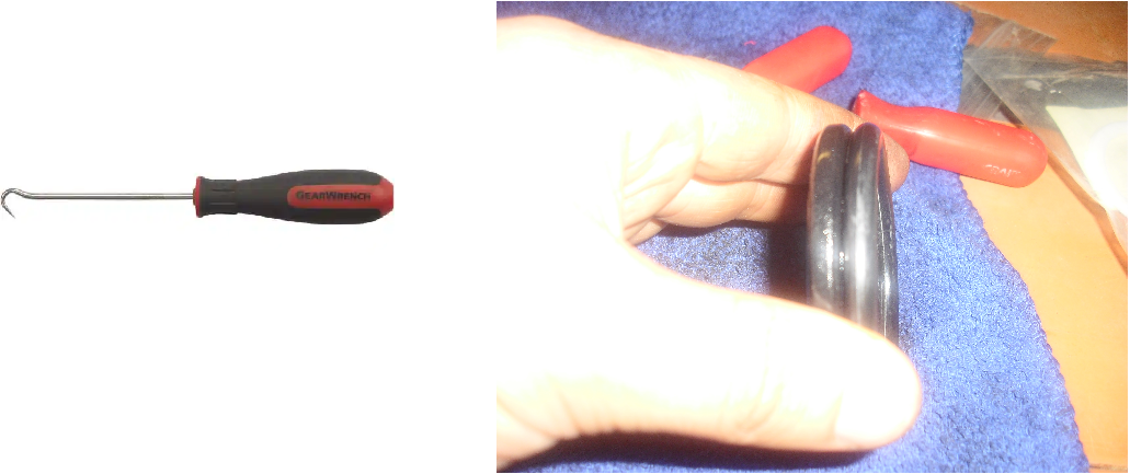
I removed the white backup ring first, then used a hooked pick to work the ring off the piston. The ring is thick and stiff, it will take a bit of work to get it off. Once off I compared this to my old one, you can see how much flatter and worn the old one looks compared to the new O-Ring
Step 6: Install the O-Ring
Lubricate the O-Ring and used to the hooked pick to reinstall. I used cutting fluid because it is thick and was handy, it worked really well, can't confirm if it is a good idea or not, usually I would use the hydro fluid, but this was more convenient at the time.
Next, install the backup ring below the O-Ring.
Step 7: Install the piston
Now, there is almost certainly a better method for this. Hopefully somebody will enlighten me in the comments. I attempted to use a ring compression tool (rated down to 2 inches) but that was not effective. I ended up placing it in the in the cylinder as snug as I could, and hitting it twice with a rubber mallet. The bevel on the casting put allowed it to go in without damaging it.
Question for more experienced maintainers: What have you done in the past? Any suggestions for a better installation method?
Step 8: install the cover
If you purchased the cover O-Rings, now would be a good time install them. The procedure should be about the same as replacing the O-Rings on the piston.
Make sure your O-Rings are lubricated and install the cover. I used the mounting screws to pull to cover evenly.
Step 9: Install the seat
Reinstall the seat mounting bolts
Step 10: TEST IT!
That's it. It is ready to test.
I hope this helps some others out! Enjoy!
I was looking around and did not see much information on repairing the 3 pt lift cylinder, so I figured I would toss some pictures and parts from my replacement for others to look at, and maybe I can learn something from y'all about the parts I was not super satisfied with.
The Problem: The 3 point hitch sinks/wont hold an implement in the air, mine was dropping my blade 32 inches to the ground in less than 2 min.
The Solution: New seals in the lift cylinder. as of today, my blade has dropped 9 inches in 48 hours, still 23 inches from the ground.
Parts Required:
When I called the dealer, they sold me 2 parts (about $12 total).
NOTE: All parts listed are for the B7200 HST 2WD, check parts diagram for your machine! I personally like using Messicks for diagrams and parts.
Kubota B7200HSTE (Hydrostatic Transmission, 2wd) Parts Diagrams
Kubota Parts Catalog Lookup. Buy Kubota Parts Online & Save!
www.messicks.com
The Piston O-Ring: 04810-08500
Back up Ring: 67211-36420
I assumed (incorrectly) that the cover was just a gasket, and I would replace it with RTV. This is wrong, I should have looked at the diagram myself. There are 2 more O-rings for the cover, I recommend replacing these as well, it is only $4 more. Thankfully mine were good enough and were able to be reused.
Cover o-ring, for cylinder: 04810-50550
Cover o-ring, to control valve: 04811-00080
The Repair Process:
Now, I am no expert mechanic, and I am certainly not an equipment specialist, but can find my way around the garage well enough. The entire process took about 3 hours, but could conceivably be done in 2 if you are not taking pictures and have some idea what you are doing. That said, hopefully more people will add some tips, tricks and process improvements in the comments, I would love to hear what you would do differently!
Step 1: Remove the seat
The seat is held on with 4 bolts. The ones in the front are 14mm and are easily removed with a socket and 6 inch extension, the ones in the rear are 12mm and were best removed with a ratchet wrench, but a socket could be used if you remove the cross member. I chose to remove it at the brackets so that I could have more room to work, and it eliminates the risk of messing up the rail alignment.
12mm bolt heads (rear) 14mm bolt heads (front)
Step 2: Clean it up
Do yourself a favor and clean the area. Especially if yours looks like mine, you don't want that getting inside, and it will let more heat off anyway (a good thing).
All I used was a nylon brush and compressed air, roughly 115 psi and only took 10 min.
NOTE: I suggest replacing the bolts prior to cleaning, this will keep the holes from getting dirt in them
NOTE: The paint is NOT resistant to harsh chemicals such as break cleaner, it will take the paint with it.
Before After
Step 2: Remove the piston cover
You will need to remove 6 bolts in total, 4 x 17mm for the cover and 2 x 14mm for the bracket below it.
Place a rag underneath the cover to catch any fluid that leaks out. Then you will need to gently pry the cover off, I used a Flathead screwdriver. This will take a bit of work, move around the edges to lift it off evenly, it may be quite snug due to the O-Ring that seals the cylinder.
Once removed, it will look like the picture on the right, and you see me pointing at the 2 O-rings used to seal the cover.
Step 4: Remove the piston
This confused me when I first started looking into it. I noticed people saying it just pulled out. This was a foreign concept to me since pistons are connected to the piston rod right? Not so with with a 3 point. The piston is floating in the cylinder, which is what lets the implements float up when they need to. Its a great system, I just never thought about it. You can see pictures of the piston/rod/cylinder in the next section for clarification.
The hardest part is figuring out how to remove the piston, some people suggested a suction cup, I saw cleaning it and using tape as another suggestion. I tried both of those out of curiosity, but they did not work for me since the piston is so porous. What I ended up doing was pressing my thumbs into the side and pulling it out, took about 20 seconds or so.
Question for more experienced maintainers: Normally, I would suggest honing the cylinder when doing rings. But I was concerned about getting excessive metal bits into the hydro fluid. The cylinder would certainly benefit from a quick honing, it has some visible scoring. I am certain it would hold better and last longer had it been honed when I did the job. What are your thoughts? Have you honed one of these before? And is here a good way to collect the metal that is removed, or will have no effect on the hydro system?
Also, lifting the hitch all the way up will draw the piston rod back, is this far enough to hone? or does the rod need lifted/propped out of the way?
Step 5: Replace the O-Ring
I removed the white backup ring first, then used a hooked pick to work the ring off the piston. The ring is thick and stiff, it will take a bit of work to get it off. Once off I compared this to my old one, you can see how much flatter and worn the old one looks compared to the new O-Ring
Step 6: Install the O-Ring
Lubricate the O-Ring and used to the hooked pick to reinstall. I used cutting fluid because it is thick and was handy, it worked really well, can't confirm if it is a good idea or not, usually I would use the hydro fluid, but this was more convenient at the time.
Next, install the backup ring below the O-Ring.
Step 7: Install the piston
Now, there is almost certainly a better method for this. Hopefully somebody will enlighten me in the comments. I attempted to use a ring compression tool (rated down to 2 inches) but that was not effective. I ended up placing it in the in the cylinder as snug as I could, and hitting it twice with a rubber mallet. The bevel on the casting put allowed it to go in without damaging it.
Question for more experienced maintainers: What have you done in the past? Any suggestions for a better installation method?
Step 8: install the cover
If you purchased the cover O-Rings, now would be a good time install them. The procedure should be about the same as replacing the O-Rings on the piston.
Make sure your O-Rings are lubricated and install the cover. I used the mounting screws to pull to cover evenly.
Step 9: Install the seat
Reinstall the seat mounting bolts
Step 10: TEST IT!
That's it. It is ready to test.
I hope this helps some others out! Enjoy!
