Questions on the care of the fuel systems in new common rail L tractors

sheepfarmer

Well-known member
Lifetime Member

Equipment
L3560, B2650, Gator, Ingersoll mower
Nov 14, 2014
4,440
654
113
MidMichigan
There are a couple of themes that keep showing up on the forum, one is bleeding fuel lines, and the other is use of fuel additives. Bleeding especially is tractor specific, and I wanted to understand how mine worked, and I have some questions. I waded through a bunch of the parts diagrams, and thought I would share those, but I still am stuck on a couple things.

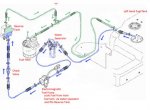
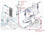
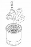
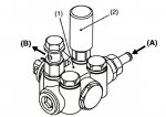
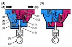
The first is a functional diagram from the wsm, but it doesn't give much clue as to what the items actually look like, and for the flow diagram it doesn't tell you whether the dotted lines mean "largely carries air", "only flows sometimes" or what.

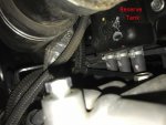
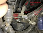
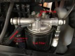
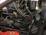
How it works is not obvious just looking at the fuel lines themselves!

Note added several weeks later: the flow diagrams ended up being revised. New and improved versions are added later further down in the thread.
 

Attachments

Last edited:

sheepfarmer

Well-known member
Lifetime Member

Equipment
L3560, B2650, Gator, Ingersoll mower
Nov 14, 2014
4,440
654
113
MidMichigan
This diagram for the L-60 tractors is from the parts catalogue (thank you Messick's for providing the images in a file format I can download) photoshopped so I could put the arrows in. It includes part of the route from the fuel tank to the injectors, and may be the most relevant part for bleeding the fuel lines after changing the fuel filter or cleaning the water separator. It looks like if you follow the Kubota directions, which are

"fill tank with fuel, open fuel cock (which is on the water separator), loosen the air vent plug on the fuel filter 2 turns, turn on key switch and wait for about 1 minute, tighten air vent plug, set hand throttle at minimum speed and turn key to "START". If the engine doesn't start, try it at several times at 30 sec intervals. Do not hold key in engine start position for more than 10 seconds continuously."

that fuel will follow this path:

From left hand fuel tank to water separator through electromagnetic pump past check valve to the reserve fuel tank. In the tractor the reserve tank is higher than these other parts, so I am thinking that fuel is pumped up to it and displaces any air in the lines out the top line and to the "T". At this point air/fuel can go either to the fuel filter to the small fitting * or take the other branch and go back to the fuel tank. *But this would put flow in the opposite direction to one of the dotted arrows so is not certain!

When Kubota draws diagrams the perspective is as if you were standing inside the engine looking out. Real photos needless to say are the reverse!

When I watched a tech bleed the 3560 when I first got it, he waited to close the air vent plug until fuel bubbled out of it. What I don't know is whether that fuel has only gone through the lines above, or if it has gone into the fuel filter by some other route to fill it up?
 

Attachments

Last edited:

sheepfarmer

Well-known member
Lifetime Member

Equipment
L3560, B2650, Gator, Ingersoll mower
Nov 14, 2014
4,440
654
113
MidMichigan
Normally when the fuel filter vent plug is closed and the engine is running or being cranked by the starter, fuel also goes by a different route:

It is sucked from the reserve tank and through the fuel cooler by the Feed Pump. This pump can only run when the engine is cranked since it works by the fuel cam. The feed pump pushes fuel to and through the fuel filter using the two bigger ports in the fuel filter housing. Fuel then goes to the Supply Pump, which is the high pressure pump for the common rail. There is a suction control valve on the input side of the supply pump that is controlled by the ECU, the main pressure-creating part is operated from the fuel cam.

Excess fuel is returned to the reserve tank to go through the fuel cooler/fuel filter loop again.
 

Attachments

Last edited:

sheepfarmer

Well-known member
Lifetime Member

Equipment
L3560, B2650, Gator, Ingersoll mower
Nov 14, 2014
4,440
654
113
MidMichigan
So, besides realizing how much I don't ever want to clog up any part of this system with algae or any other substance, I am still not totally certain what happens during the initial filling and bleeding process, and hoping someone who has looked at the inside of the fuel filter housing can clarify.

Seems like if you get done cleaning the water separator and reinstall it (empty) and change the fuel filter and install new one (empty), open fuel cock and open the air vent on fuel filter, you should first see the water separator fill with fuel when you turn the key on, which should start the electromagnetic pump. Air should be pushed out the air vent on the fuel filter for a while, is there a specific hole or is it through the threads? When fuel reaches the fuel filter can it access the filter portion and pass through it and then exit via either the input line or the output to the supply pump? Basically the question is when you see fuel bubbling out near this screw is it because the fuel filter is full, or just that that path so far has air removed?

My first guess is not full, and that it requires the next step, cranking to activate the feed pump to suck fuel out of the reserve tank and push it through to the supply pump and on to the injectors.

The parts diagram of the fuel filter housing is mum on this issue, so anyone that has looked at it, thoughts would be appreciated. Thanks!
 
Last edited by a moderator:

sheepfarmer

Well-known member
Lifetime Member

Equipment
L3560, B2650, Gator, Ingersoll mower
Nov 14, 2014
4,440
654
113
MidMichigan
I'm only hearing crickets at this end, but supposing not too many people have looked upside down at this housing when they were changing their fuel filter on an L60, but maybe there are some similarities to cars as Coach pointed out earlier. Here are some pictures of the filter and filter housing, but it just doesn't show what's inside. The bleeder plug has an O ring and seems to have a groove in it. The fuel filter itself has 2 O rings. All this points to Kubota having a very specific fuel flow in mind, both normally and during bleeding, but exactly what is not clear.

Edit for clarity:
In run mode:
Fuel comes from the main tank, through the water separator, through the Electromagnetic fuel pump to the reserve tank, through the fuel cooler, through the Feed Pump, into the outside of the fuel filter (small holes), out of the large hole in the middle, to the supply pump and then to the common rail.

In purge mode:
With the bleeder screw open 2 turns, fuel comes from the tank, through the water separator, etc into the outside of the filter, out of the large middle hole then out the vent line (open bleeder) and onto the T and points beyond, air and then fuel is pushed out of the vent back to the tank.


In practical terms this boils down to is there any advantage to waiting the full minute to close the bleeder plug down in case it is still filling up the fuel filter, even though it may be spitting out a mixture of air and diesel?

Edit:
The reason for the one min is to allow enough time for fuel to be pushed through the system, including the fuel cooler, to saturate the filter element and to purge all of the air out.


Any input would be appreciated! Thanks
 

Attachments

Last edited:
Oct 8, 2014
623
4
16
oregon
I can only tell you about Stupid Duty's but... you just cycle the key to bleed. Those motors have two fuel filters and I've learned to replace one at a time and cycle until it starts. I can actually hear the air bubbling back into the tank. In other words the fuel system is a continuous loop.
 

sheepfarmer

Well-known member
Lifetime Member

Equipment
L3560, B2650, Gator, Ingersoll mower
Nov 14, 2014
4,440
654
113
MidMichigan
I can only tell you about Stupid Duty's but... you just cycle the key to bleed. Those motors have two fuel filters and I've learned to replace one at a time and cycle until it starts. I can actually hear the air bubbling back into the tank. In other words the fuel system is a continuous loop.
It sounds similar. This one certainly has at least one loop. Two canister filters?

Do you remember about a year or two ago you mentioned how water cratered the Bosch high pressure pumps? Can you add any info or where you found that reference? I have tried searching to figure out which parts are affected the most, but no luck.
 
Oct 8, 2014
623
4
16
oregon
Two canister filters?

Do you remember about a year or two ago you mentioned how water cratered the Bosch high pressure pumps? Can you add any info or where you found that reference? I have tried searching to figure out which parts are affected the most, but no luck.
Yes, 2 filters. One is before the HPFP and I believe a larger micron, i.e. pre filter. The other is on the high pressure side and a finer filter but I could have these backward.

Search any diesel truck site and you will find blown HPFP systems. Typically it's someone who put DEF fluid in the fuel tank but H2O will do it just as fast. The tolerances on those pumps, Bosch, are so tight they need the diesel for lubricant. It's another reason to run a fuel additive for lubricity but honestly 2 cycle oil will do the same. Not trying to start a flame thread over the 2 cycle but I did learn that from someone running older log trucks. I don't use those sites anymore but it was the same user ID.
 
Oct 8, 2014
623
4
16
oregon
Great write up and confirms that I never want this system. Way too many ways to go south...
7.3 Fords, older Cummins are all pretty bulletproof. On the other hand I get the same or better mileage and twice the power. I smile pulling at GCVW and passing semi's on the uphill. 2018 SD's have about 25% more power than mine. We drive around the speed limit, have fancy elctro/hydro trailer brakes + exhaust brake. In other words having the power doesn't mean we are reckless.
 

sheepfarmer

Well-known member
Lifetime Member

Equipment
L3560, B2650, Gator, Ingersoll mower
Nov 14, 2014
4,440
654
113
MidMichigan
One of the complications as far as understanding the fuel flow during bleeding is the Feed Pump. When the engine is running, it receives fuel from the reserve tank (which has already gone through water separator) and that has been through the fuel cooler. See diagram below. It then pushes that fuel through the fuel filter to the Supply Pump.

What is not clear is how fuel gets to the fuel filter when the engine is not running. E.g. during the bleeding operation. The description from the wsm is attached. It would seem to me given the two check valves inside, that fuel cannot pass through this pump even with the aid of the pressure created by the Electromagnetic Pump, but at the moment that would be the $64,000 question. That means any fuel I saw during bleeding would have come from the direction of the T. If it can pass through when the pump is not running, the dashed arrow (see post 1) is directed correctly. To be continued.

Note that the priming pump referred to in the text is not present in the parts diagrams nor is on my tractor. Nice idea though:rolleyes:
 

Attachments

  • Like
Reactions: 1 user

North Idaho Wolfman

Moderator
Staff member
Lifetime Member

Equipment
L3450DT-GST, Woods FEL, B7100 HSD, FEL, 60" SB, 743 Bobcat with V2203, and more
Jun 9, 2013
28,286
4,853
113
Sandpoint, ID
This is my guess:
If you notice the valves in the feed pump, this allows flow to pass through it if there is pressure applied to the input of the pump.
This is why they say to turn the key on as the Electro Mechanical pump creates enough pressure and flow to open the valves thus pushing air and fuel threw the pump and to the filter where it is bleed out back to the tank.
If someone wanted to confirm this, all they would have to do is remove the line off the output of the feed pump, turn on the key and see if you get flow out of the feed pump.
 
Last edited:

Newlyme

Active member
Lifetime Member

Equipment
M4900 w/loader, finish mower, tiller, auger, rake. BX24 w/loader, backhoe
May 27, 2015
632
62
28
Nelson Ohio USA
This is my guess:
If you notice the valves in the feed pump, this allows flow to pass through it if there is pressure applied to the input of the pump.
This is why they say to turn the key on as the Electro Mechanical pump creates enough pressure and flow to open the valves thus pushing air and fuel threw the pump and to the filter where it is bleed out back to the tank.
If someone wanted to confirm this, all they would have to do is remove the line off the output of the feed pump, turn on the key and see if you get flow out of the feed pump.
I am not familiar with the Kubota CR fuel system but, I have owned a few and still have one VW diesel with a CR system. Your thought process here is the actual process that MUST be used when changing the fuel filter in that system or HPFP damage will occur. The only difference from what you are saying is in the VW you must use a computer to turn on one of the three fuel pumps to purge air from the system.
 

sheepfarmer

Well-known member
Lifetime Member

Equipment
L3560, B2650, Gator, Ingersoll mower
Nov 14, 2014
4,440
654
113
MidMichigan
NIW I think your idea is more plausible than my version of running the fuel from the reserve tank through the T and "backwards" into the fuel filter.

Your idea only requires one assumption, that the Feed Pump will pass fuel when not on. Well maybe two, that the Electromagnetic Pump is capable of pushing fuel up to the Reserve Tank, then down and around the Fuel cooler, in spite of a sizable air leak at the top of the Reserve Tank.

The "through the T" path requires a fancy redesign of the fuel filter holder to make sure that fuel goes into the right part of the filter to get filtered, and air to exit via the plug threads, as well as assuming that the dashed arrow in the shop manual means sometimes goes in the backwards direction.

I forget whose principal it was, but choose the simplest hypothesis to test first. I like your experiment, but on my tractor it will have to wait until a fuel filter change or the lines get replaced, which is due soon.

All things considered, if I don't hear anything different I'll modify those diagrams to shift my hand drawn arrows.

Thank you NIW!
 

Daren Todd

Well-known member
Lifetime Member

Equipment
Massey Ferguson 1825E, Kubota Z121S, Box blade, Rotary Cutter
May 18, 2014
8,961
4,329
113
Vilonia, Arkansas
Here's what I've found with bleeding common rail fuel systems. If the equipment is run out of fuel. It is a bear to bleed them. Hence why most computer systems shut down an engine on certain low fuel rail pressure codes.

From what I've seen on a few different brands of engines, is they have a bypass valve back to the fuel tank in and around a fuel filter base. Or near the injection pump. If it's an electric fuel pump. Just cycle the key a few times to fill the fuel filters and purge the air.

With a mechanical fuel pump. Prime till you feel good pressure then keep going for a bit. Sometimes you can here the air bubble in fuel tank when it purges the air. Just depends how close you are to the fuel tank.

Your fuel pumps are low pressure just to feed fuel to the injection pump. The fuel injection pump bumps up the fuel pressure to what ever is needed to pop the injectors off.

Where it gets to be a real pain sometimes, is when someone slaps a filter on, doesnt take the time to bleed it, starts the unit, and airlocks the injection pump, or the common rail portion. The tier 4 injection systems run some crazy high pressures. And have coated connections to help seal the fuel injection lines. Crack an injection line loose, and the injection line needs to replaced. This varies by manufacturer. So gone are the days of cracking a fuel line at the injector to bleed the air out :rolleyes:

So my disclaimer :D If you happen to air lock one. You need to contact the dealer, and see what there procedure is, if they will tell you.

Some of my equipment, I can remove a pressure relief valve, and bleed the air out of the injection pump. On others, I've had to remove the injection line from the injection pump to the fuel rail, bleed the air out of the injection pump. Then replace the line with a new one so it will seal correctly.