B7100-HST hydraulic confusion

torch

Well-known member

Equipment
B7100HSD, B2789, B2550, B4672, 48" cultivator, homemade FEL and Cab
Jun 10, 2016
2,595
837
113
Muskoka, Ont.
I'm trying to figure out the hydraulics in anticipation of adding a FEL.

The WSM calls the hydraulic system control type a "closed centre type" under the general specifications. However, the pump seems to be a fixed-displacement gear pump and in the description of the control lever functions, it states

"with the hydraulic control lever at neutral, oil is pressure-fed from the pump through the space between the valve body and the spool big end to the body cover. It then returns to the return port of the valve body."

Is this not the description of an open centre type?

Next question: I have read in at least two threads here that the B7100-HST has a 4 gpm hydraulic pump, as opposed to the 3 gpm pump of the original B7100. However, the WSM indicated the pump delivers 11.2 lpm, which is actually less than 3 gpm. Is there any documented update at a specific serial number or date? EG: The WSM I have has an inserted section ("G1") documenting a 1990 change of the HST. Or is this a matter of an honest error being repeated often enough to seem true?

Several threads mention the possibility of swapping in the higher volume pump from a B8200. But apparently there's at least 3 different B8200 pumps. Can anyone confirm that the correct pump would be the one driven from the injection pump, part number 67111-76103?

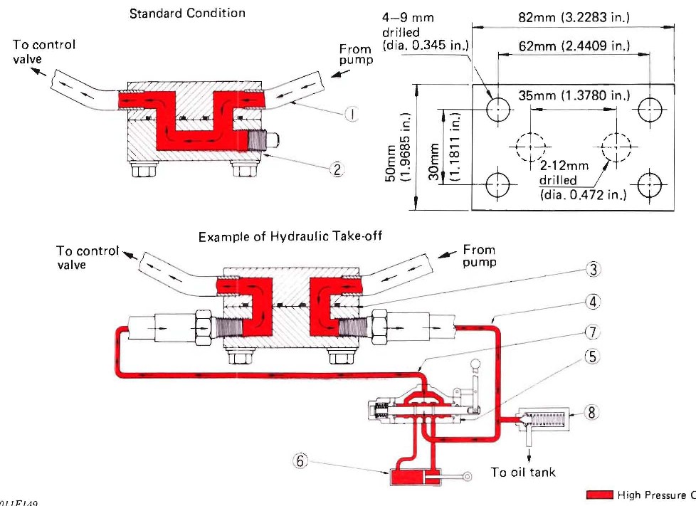
The diverter valve under the seat can be used to operate a second hydraulic function (single acting) from the existing control valve instead of lifting the 3ph. Alternatively the "hydraulic block" can be tapped by removing the cover and replacing it with the "impement hydraulic cover". I assume this is a Kubota-specific part? Does it only come with Kubota-brand implements? There's a dimensioned sketch in the WSM adjacent to the flow diagrams, and the diagrams seem to show the o-rings are in the retained half of the block -- is the cover as simple as drilling/tapping some holes in a block of steel?

Do I understand correctly that to tap into the hydraulic block would then necessitate an implement open centre spool valve fed from the pump side of the hydraulic block and "power beyond" function piped back to the 3ph side of the hydraulic block, plus a third line from the implement relief valve discharge back into the reservoir?

How does one normally deal with fluid flow to remove the FEL? Mount the spool valve to the FEL and couple the tractor side hoses to each other to complete the circuit? Or is it preferable to mount the spool valve to the tractor so there is no chance of dead-heading the hydraulic system?

I will probably have more questions, but my grandson just arrived and hopped up onto my knee...
 
Last edited:

North Idaho Wolfman

Moderator
Staff member
Lifetime Member

Equipment
L3450DT-GST, Woods FEL, B7100 HSD, FEL, 60" SB, 743 Bobcat with V2203, and more
Jun 9, 2013
28,722
5,132
113
Sandpoint, ID
Open center system, Must be a typo in manual you have (not uncommon).

just a block of aluminum will work for the tap plate.

and don't bother with worrying about changing the pump, the pump on it will work fine.

Also don't worry about the GPM #'s, as those #'s were rounded and were specs from when the pump was new, it will be close to whatever they say and that's fine.
 

torch

Well-known member

Equipment
B7100HSD, B2789, B2550, B4672, 48" cultivator, homemade FEL and Cab
Jun 10, 2016
2,595
837
113
Muskoka, Ont.
Next question: I have read in at least two threads here that the B7100-HST has a 4 gpm hydraulic pump, as opposed to the 3 gpm pump of the original B7100. However, the WSM indicated the pump delivers 11.2 lpm, which is actually less than 3 gpm. Is there any documented update at a specific serial number or date? EG: The WSM I have has an inserted section ("G1") documenting a 1990 change of the HST. Or is this a matter of an honest error being repeated often enough to seem true?
I have answered my own question, now that I have built the FEL.

I used 2" diameter cylinders with 1-1/4" rods. Therefore, extending a cylinder requires 50.265 cu. in. of fluid, and retracting requires 30.63 cu. in.

At WOT, it takes 56 seconds to fully raise and then immediately fully lower the boom 4 complete cycles. Since there are two lift cylinders, that's a total of 647.2 cu. in. or 2.8 USG of hydraulic fluid in 56 seconds. Therefore the pump can supply almost exactly 3 USGpM.
 

Del1978b7100HD

New member

Equipment
B7100 HST 1984, BX5450
Jan 11, 2019
6
0
0
Zeeland MI
Thanks for all of the info. Please confirm that I will need to run a hose to the reservoir from the, Newly Purchased duel spool, Hydraulic control valve from the port tagged relief valve or if it has a internal relief valve am I good?
Thank you.
 

torch

Well-known member

Equipment
B7100HSD, B2789, B2550, B4672, 48" cultivator, homemade FEL and Cab
Jun 10, 2016
2,595
837
113
Muskoka, Ont.
Thanks for all of the info. Please confirm that I will need to run a hose to the reservoir from the, Newly Purchased duel spool, Hydraulic control valve from the port tagged relief valve or if it has a internal relief valve am I good?
Thank you.
I don't know what you bought. I'd be happy to look it up if you told me make and model.

However, I believe 99% of all such control valve assemblies will have a built-in relief valve. You will require 3 lines:

1. Line from pump side of hydraulic block to spool valve assembly Inlet Port.

2. Line from spool valve assembly Power Beyond port to 3ph side of hydraulic block.

3. Line from spool valve assembly Return or Reservoir port to the tractor's reservoir.

Internally, a built-in relief valve will be piped from 1 to 3. If line 1 pressure exceeds the relief valve set-point, then it opens and bleeds fluid back to the reservoir through line 3.

NOTE: This limits the pressure available on the entire system. The relief valve is in parallel with the 3ph relief valve. If the new spool valve assembly relief valve is set to a lower pressure than the existing 3ph relief valve, then the maximum pressure available to the 3ph will be limited to the new relief valve setting.

For example, if the 3ph setting is 2,000 psi, and the spool valve setting is 1,500 psi, then the maximum pressure that can be developed on any part of the hydraulic system is 1500 psi.

If there was no 3rd line, and the new relief valve discharge was piped to the Power Beyond line, then the maximum pressure on the new spool valve assembly could be compounded if both FEL and 3ph are operated at the same time. That is, the peak pressure possible on the FEL in the above example would be 3,500psi, although the peak pressure on the 3ph would remain 2,000psi.

So the 3rd line is absolutely necessary.
 

Del1978b7100HD

New member

Equipment
B7100 HST 1984, BX5450
Jan 11, 2019
6
0
0
Zeeland MI
Thanks Torch, the New control valve I ordered from Northern Tool. I ordered the one that has a float valve in it to allow the blower to float. the other control will mange the snow shoot.

Prince Hydraulic Valve - 8 GPM, Model# MB21GB5C1
 

torch

Well-known member

Equipment
B7100HSD, B2789, B2550, B4672, 48" cultivator, homemade FEL and Cab
Jun 10, 2016
2,595
837
113
Muskoka, Ont.
Thanks Torch, the New control valve I ordered from Northern Tool. I ordered the one that has a float valve in it to allow the blower to float. the other control will mange the snow shoot.

Prince Hydraulic Valve - 8 GPM, Model# MB21GB5C1
On the NT page for that valve is a downloadable PDF manual (https://www.northerntool.com/images/downloads/manuals/204603.pdf). It is generic for all variations of the MB series, but the first page states:


"RELIEF VALVE: AN ADJUSTABLE RELIEF VALVE CARTRIDGE IS STANDARD ON ALL 'MB' MODELS. THE STANDARD FACTORY SETTING IS 2500 PSI @ 6 GPM. STANDARD ADJUSTMENT RANGE IS 2000 PSI TO 3500 PSI. "

Page 2 describes how to set it up for Power Beyond function:

"OPTIONAL POWER BEYOND OPERATION: INSTALL THE HIGH PRESSURE CARRY OVER PLUG (1/4-18 BSPT) INTO THE INTERNAL THREADS TO THE
INSIDE OF THE "C" PORT. CONNECT A HYDRAULIC LINE FROM THE "C" PORT TO A DOWN STREAM FUNCTION AND THE "T" PORT TO TANK. WITH ALL SPOOLS CENTERED, OIL FLOW IS DIRECTED TO THE POWER BEYOND PORT 'C' FOR USE BY THE DOWNSTREAM FUNCTION. WHEN A SPOOL IS SHIFTED, OIL WILL BE DIRECTED TO A WORK PORT AND THE RETURN FLOW TO TANK."

The diagram on Page 2 is a little bit confusing, however I think what they are trying to show is how PB works with two sets of valves. The right hand valve set is configured for Power Beyond. The left hand valve set in that diagram is just showing how to configure the last valve set in a chain. Disregard that for your application -- the last valve in your chain will be the 3ph control that is already built into the tractor. Configure your new valve set as shown in the right hand set in that diagram. That is:

1. Hose from tractor's pump-side hydraulic block port to new spool valve set "I" port.

2. Install internal plug inside spool valve set "C" port. Hose from "C" port to 3ph side of tractor's hydraulic block.

3. Hose from spool valve set "T" port to the tractor's reservoir. On the B7100, this requires installing a 1/2" nipple and tee in the hydraulic oil fill opening. Move the plastic cap to the top of the tee and pipe the return line into the side of the tee.
 

torch

Well-known member

Equipment
B7100HSD, B2789, B2550, B4672, 48" cultivator, homemade FEL and Cab
Jun 10, 2016
2,595
837
113
Muskoka, Ont.
I don't know if you are aware of this, but to use the hydraulic block as I have described, you need to swap out the top to redirect the flow. The original looks like this:


You can make your own by drilling and tapping a suitable block of steel or even possibly aluminium, like so:


Here are the details:


(EDIT: for those led here by Google, see also https://www.orangetractortalks.com/...ock-diverter-70060-00360-or-70070-00385.56471 to get one.)
 
Last edited:
  • Like
Reactions: 1 user

Del1978b7100HD

New member

Equipment
B7100 HST 1984, BX5450
Jan 11, 2019
6
0
0
Zeeland MI
Yes, I did realize I would have to make a new block. Can it be as simple to tap in from the front as apposed from the side. By the way your responses have been awesome/detailed/really amazing thanks for your home work.
 

North Idaho Wolfman

Moderator
Staff member
Lifetime Member

Equipment
L3450DT-GST, Woods FEL, B7100 HSD, FEL, 60" SB, 743 Bobcat with V2203, and more
Jun 9, 2013
28,722
5,132
113
Sandpoint, ID
Yes, I did realize I would have to make a new block. Can it be as simple to tap in from the front as apposed from the side. By the way your responses have been awesome/detailed/really amazing thanks for your home work.
Yes the factory blocks were taped from the front.
And just for clarity, you do realize that its a new block with no sideways (bypass) path that you need. ;)
 

Del1978b7100HD

New member

Equipment
B7100 HST 1984, BX5450
Jan 11, 2019
6
0
0
Zeeland MI
Yes , I do realize this, thanks. I will try to take some pics of progress. I did try down lading but jpg pics may be to large. I think I get my Control valve next Monday. thanks again.
 

North Idaho Wolfman

Moderator
Staff member
Lifetime Member

Equipment
L3450DT-GST, Woods FEL, B7100 HSD, FEL, 60" SB, 743 Bobcat with V2203, and more
Jun 9, 2013
28,722
5,132
113
Sandpoint, ID
Yes , I do realize this, thanks. I will try to take some pics of progress. I did try down lading but jpg pics may be to large. I think I get my Control valve next Monday. thanks again.
You need at least 5 posts to upload photos, so one more post and you can do it. ;)
 

torch

Well-known member

Equipment
B7100HSD, B2789, B2550, B4672, 48" cultivator, homemade FEL and Cab
Jun 10, 2016
2,595
837
113
Muskoka, Ont.
Can it be as simple to tap in from the front as apposed from the side.
Yes, but it does get a bit crowded with two fittings out the front. I have the supply coming out the front (which leaves more room for changing the fuel filter) and the return going into the rear side.

I also drilled and tapped the forward side, so my supply has two outlets. It's plugged off but provides a port where I could connect a pressure gauge if I ever wanted to. It's not necessary though.
 

Russell King

Well-known member

Equipment
L185F, Modern Ag Competitor 4’ shredder, Rhino tiller, rear dirt scoop
Jun 17, 2012
4,668
1,003
113
Austin, Texas
Torch,
I feel like a chicken watching a card trick when looking at your picture of the two blocks and the schematic!

Is the block on the right the new block? Is it finished? Where is the second hole on the large face?

Please enlighten me on what you are showing since I seem to weak minded to follow you.


Sent from my iPad using Tapatalk
 

torch

Well-known member

Equipment
B7100HSD, B2789, B2550, B4672, 48" cultivator, homemade FEL and Cab
Jun 10, 2016
2,595
837
113
Muskoka, Ont.
This image shows either side of the new block. I made 2 of them (someone else on this board needed one at the same time as I was making my own):


The block on the left is showing the sealing face that will be bolted to the existing half with the o-rings. The large hole on the lower end is connected internally to a tapped hole on the face the block is resting on. The large hole on the upper end is connected internally to the tapped hole visible on the top of this block.

The upper large hole and the lower large hole are NOT connected. The original block you are replacing has them connected so that the fluid passes through the block to the 3ph. This replacement block interrupts that flow and sends it through your new auxilliary spool valve instead. When your new valves are both in the neutral position, THEY return the fluid through the Power Beyond port to this block and from there on to the 3ph.

The right hand block shows the face that is exposed to the world when installed. The tapped hole on the top is the same as with the left hand block. The tapped hole visible on the face is connected internally to the top hole AND the upper large hole shown on the left hand block. In other words, that passage has two tapped outlets.

It only needs one, I just made it that way for flexibility of design. The block can be installed either way around.

The 4 smaller diameter holes are not connected internally to anything; they are just mounting holes.

Clear as mud?
 
Last edited:

torch

Well-known member

Equipment
B7100HSD, B2789, B2550, B4672, 48" cultivator, homemade FEL and Cab
Jun 10, 2016
2,595
837
113
Muskoka, Ont.
And just for fun, since you have me digging through old photos, here's the manufacturing process:


Russell King

Well-known member

Equipment
L185F, Modern Ag Competitor 4’ shredder, Rhino tiller, rear dirt scoop
Jun 17, 2012
4,668
1,003
113
Austin, Texas
Torch,

Thanks for the explanation. I thought the left block was the old block (same as in picture with tractor) and the right was the new block-same side showing.

Now that I know it is top and bottom views of the new blocks that makes sense.


Sent from my iPad using Tapatalk
 

torch

Well-known member

Equipment
B7100HSD, B2789, B2550, B4672, 48" cultivator, homemade FEL and Cab
Jun 10, 2016
2,595
837
113
Muskoka, Ont.
Cool! Looks great, glad to hear it all worked out for you.