Hey guys,
Sorry about the pics below not being perfect. I'm currently separated from my tractor by a flooded bridge so I'm hoping they're good enough for the advice sought!
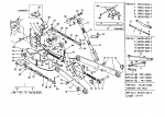
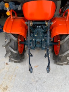
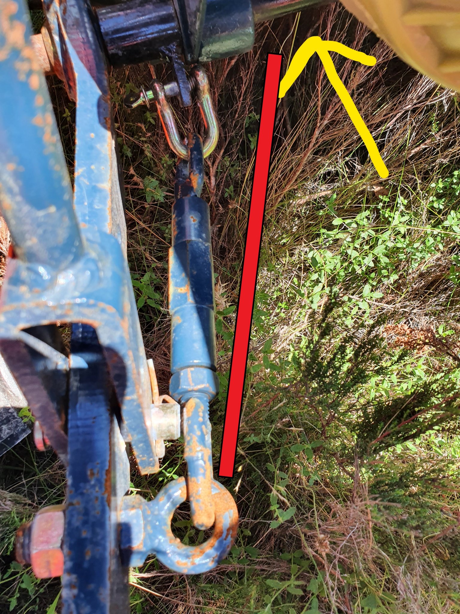
I'm a newby and my tractor is a remanufactured Kubota B7001 (grey import into Australia, I believe it's an Asian market model number and almost identical to the B7100). I'm pretty sure the adjustable / turnbuckle limiting arms on for the lower 3 Point arms were attached in the wrong spot when I got it. They were attached right next to the ball joints mounting the lower arms to the tractor, hence even on their tightest (shortest) setting they were loose, the implements moved sideways and the lower arms rubbed on the rear tyres. The close up pic of the left side setup shows how it came and the yellow arrow is where I moved the collar that the limiting arms attach to. I also flipped the collars over so the D shackle mounts to the outer edge of them and now the limiting arms sit about where the red line is I've drawn on the photo. It has enough adjustment and controls the movement so there is no more rubbing.
The bit that seems wrong however, is that in the previous setup, the collars the limiting arms mount to were also spacers between the ball joints on the lower arms and the tractor mounts, so it held the lower 3 Pt arms in a pretty fixed position on the tractor end. Now with the collars in between the 2 tractor mounts / tractor eyelets, the ball joints on the tractor end of the 3 Pt arms are free to move about 4cm (1 1/2") left or right. In fact if one moved inwards, the whole rod that mounts the assembly to the tractor could move across the same distance so the opposite side could move outwards twice as far (about 8cm or 3"). I used the flail mower for a few hours like that and didn't have any problems (nothing seemed to move), but it just seems like it is missing some spacers?
Sorry about the pics below not being perfect. I'm currently separated from my tractor by a flooded bridge so I'm hoping they're good enough for the advice sought!
I'm a newby and my tractor is a remanufactured Kubota B7001 (grey import into Australia, I believe it's an Asian market model number and almost identical to the B7100). I'm pretty sure the adjustable / turnbuckle limiting arms on for the lower 3 Point arms were attached in the wrong spot when I got it. They were attached right next to the ball joints mounting the lower arms to the tractor, hence even on their tightest (shortest) setting they were loose, the implements moved sideways and the lower arms rubbed on the rear tyres. The close up pic of the left side setup shows how it came and the yellow arrow is where I moved the collar that the limiting arms attach to. I also flipped the collars over so the D shackle mounts to the outer edge of them and now the limiting arms sit about where the red line is I've drawn on the photo. It has enough adjustment and controls the movement so there is no more rubbing.
The bit that seems wrong however, is that in the previous setup, the collars the limiting arms mount to were also spacers between the ball joints on the lower arms and the tractor mounts, so it held the lower 3 Pt arms in a pretty fixed position on the tractor end. Now with the collars in between the 2 tractor mounts / tractor eyelets, the ball joints on the tractor end of the 3 Pt arms are free to move about 4cm (1 1/2") left or right. In fact if one moved inwards, the whole rod that mounts the assembly to the tractor could move across the same distance so the opposite side could move outwards twice as far (about 8cm or 3"). I used the flail mower for a few hours like that and didn't have any problems (nothing seemed to move), but it just seems like it is missing some spacers?