Dave
Yes, this is a tough one. At least three configurations: the representation in the L175 original wiring diagram, the nebulous "as modified" in reality, and what could be in the near future.
Metric 3 conductor assuming 75 deg C insulation should handle 25 amps. Maybe add fusible link(s) later but for now too confusing (my opinion).
Mechanical voltage regulator should be okay. Main job is to supply just the right amount of current to the alternator field to meet load demand at given voltage. I don't see this little tractor using a lot of electrical power.
Can't tell if this machine has original wiring or has been modified. So color codes now have no meaning for me. Best way to describe is an end to end description.
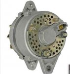
Obviously the three-terminal regulator does the job. A six-terminal regulator would allow connection of the charging lamp, and original wiring to ignition switch. The original dynamo had terminals N (Neutral), E (Earth, chassis, ground, -12V), F (Field), and B (Battery +12V). The new generator has the same terminals. New connector for F, E, N to be spliced onto existing wiring.
Loss of oil pressure light, as you said, is probably a fuse, but could be bulb.
Need to caution that any work needs to be done with battery disconnected so as not to destroy alternator/regulator.
Question at this point is if a charging lamp is desired, then go to a six-terminal voltage regulator like original. If no charging lamp, and three-terminal regulator, new wiring instructions, not by color, but by end to end.
My preferred way would be to go with a six-terminal replacement regulator to match the original setup and connector. If no charging lamp, then I would add a voltmeter to the panel.
Would be pleased to hear your thoughts.