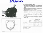
My S2600 WSM refers to a "Fuel tightness of pump element" test
Has anyone done one of these tests of a Bosch/Diesel Kiki K type injection pump? The purpose of the test is to find out if each element of the fuel injection pump is delivering appropriate pressure to the injector line, without having to pull the pump off the engine.
The way it is described in my WSM, if I follow the instructions, it looks like I will get hydraulic lock which could destroy something.
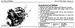
A screenshot of the manual is below, but in summary the process Kubota says to follow is:
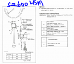
* Attach a 30 MPa (4500 psi) gauge via a 600mm long fuel line to the delivery valve holder (there's a drawing of the gauge and line on another page also attached below).
* Set the throttle at idle.
* Turn the engine over on the starter (the injector lines are removed, so it won't start).
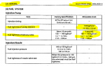
* If the pressure exceeds 14.7 MPa/2133psi, then that element is good.
(The manual also describes a separate process for testing the delivery valve fuel tightness like those below - and it involves hand turning the flywheel, not cranking over using the starter.)
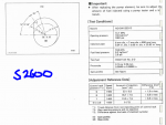
Other manuals for engines using what I guess is the same sort of pump recommend a process that doesn't rely on cranking on the starter motor. E.g. Kubota 68mm stroke engines:
Their instruction is basically as above, but instead of using the starter motor, turn the flywheel counterclockwise, presumably by hand. Also looked at engines with similar pumps. None say to use the starter to crank over. Instead they recommend hand turning the engine counterclockwise, and if the pressure doesn't get to a certain level, then the element is bad.
See image below.
So if you've managed to read this far, would you mind advising me, is my S2600 manual wrong, and instead of cranking with the starter motor, I should use the process in the 68mm stroke engine manual? Thank you all.
(BTW I'm looking at doing this test because the engine note is uneven under load, I think I've covered all other factors for troubleshooting - injectors rebuilt, checked compression, done leakdown test, checked valve clearances etc etc, but I don't want to pull the pump off and send it for testing if it is actually OK).
Has anyone done one of these tests of a Bosch/Diesel Kiki K type injection pump? The purpose of the test is to find out if each element of the fuel injection pump is delivering appropriate pressure to the injector line, without having to pull the pump off the engine.
The way it is described in my WSM, if I follow the instructions, it looks like I will get hydraulic lock which could destroy something.
A screenshot of the manual is below, but in summary the process Kubota says to follow is:
* Attach a 30 MPa (4500 psi) gauge via a 600mm long fuel line to the delivery valve holder (there's a drawing of the gauge and line on another page also attached below).
* Set the throttle at idle.
* Turn the engine over on the starter (the injector lines are removed, so it won't start).
* If the pressure exceeds 14.7 MPa/2133psi, then that element is good.
(The manual also describes a separate process for testing the delivery valve fuel tightness like those below - and it involves hand turning the flywheel, not cranking over using the starter.)
Other manuals for engines using what I guess is the same sort of pump recommend a process that doesn't rely on cranking on the starter motor. E.g. Kubota 68mm stroke engines:
Their instruction is basically as above, but instead of using the starter motor, turn the flywheel counterclockwise, presumably by hand. Also looked at engines with similar pumps. None say to use the starter to crank over. Instead they recommend hand turning the engine counterclockwise, and if the pressure doesn't get to a certain level, then the element is bad.
See image below.
So if you've managed to read this far, would you mind advising me,
is my S2600 manual wrong, and instead of cranking with the starter motor, I should use the process in the 68mm stroke engine manual? Thank you all.(BTW I'm looking at doing this test because the engine note is uneven under load, I think I've covered all other factors for troubleshooting - injectors rebuilt, checked compression, done leakdown test, checked valve clearances etc etc, but I don't want to pull the pump off and send it for testing if it is actually OK).
Attachments
-
 47.7 KB Views: 473
 -
 165 KB Views: 495
 -
 74.6 KB Views: 448
Last edited: