Reviving a G1900

Hugo Habicht

Well-known member
Lifetime Member

Equipment
G1900
Jun 24, 2024
519
662
93
Ireland
If you disconnect the linkages you should be able to push the deck back far enough under the tractor to get the drive shaft off at the front. Then you should be able to move it in any direction to reach the grease nipple. Maybe you can replace it with an angled version to be able to reach it without that maneuver.

Don't neglect the servicing, greasing. See what damage it did to my front axle.
 
Last edited:
  • Like
Reactions: 1 user

lmichael

Well-known member

Equipment
Kubota G2160
Apr 23, 2021
714
341
63
Rockford IL area
If you disconnect the linkages you should be able to push the deck back far enough under the tractor to get the drive shaft off at the front. Then you should be able to move it in any direction to reach the grease nipple. Maybe you can replace it with an angled version to be able to reach it without that maneuver.

Don't neglect the servicing, greasing. See what damage it did to my front axle.
That is how I do it. I cannot get the collar on the PTO off with the mower deck in place. Literally cannot fit myself up under there to get my hand in position. So, I jack the back end of the machine up really high, with the linkages disconnected, I then slide the deck backward and off the slip joint, once it's slid out and dragged away I can then get the collar released for the PTO shaft to the mower. A little convoluted but it's the only way this old fart can handle it :D
 

Hugo Habicht

Well-known member
Lifetime Member

Equipment
G1900
Jun 24, 2024
519
662
93
Ireland
That is how I do it. I cannot get the collar on the PTO off with the mower deck in place. Literally cannot fit myself up under there to get my hand in position. So, I jack the back end of the machine up really high, with the linkages disconnected, I then slide the deck backward and off the slip joint, once it's slid out and dragged away I can then get the collar released for the PTO shaft to the mower. A little convoluted but it's the only way this old fart can handle it :D
That sounds pretty complicated to reach one grease point. On the G1900 there really is enough space from the side. Have you tried turning the front wheels for a bit of extra space?
 

lmichael

Well-known member

Equipment
Kubota G2160
Apr 23, 2021
714
341
63
Rockford IL area
It's on the U Joint for the mower drive shaft. Could turn the wheels until the cows come home, sadly they way that zerk is jammed in there, you have to pull the shaft and angle the end at 90deg to get the fitting on there
 

Hugo Habicht

Well-known member
Lifetime Member

Equipment
G1900
Jun 24, 2024
519
662
93
Ireland
Is that a straight one? Then you could replace it with an angled version. This is accessible with a normal grease gun head.

It is a u-joint from a deck I just repaired. It has to point in the right direction, of course. So buy a bunch of them (Aliexpress) and try out which one is fine when tightened or degrease everything and use Loctite.

Is it the right PTO shaft for this deck? Maybe you have to shorten the sliding parts ever so slightly.
 

Attachments

Last edited:

lmichael

Well-known member

Equipment
Kubota G2160
Apr 23, 2021
714
341
63
Rockford IL area
When I have the shaft out I'll run to my farm supply store and see what I can find. Honestly it is frustrating. I may not even get to this for awhile or even this year. Lots is riding on whether or not they find the "Big C" when I go to the urologist in 10 days
 
  • Sad
Reactions: 1 user

Hugo Habicht

Well-known member
Lifetime Member

Equipment
G1900
Jun 24, 2024
519
662
93
Ireland
Rear wheel steering repair

There are are few parts that can wear or can be damaged:

08101-06205 bearing drive shaft, 2x 6205
09502-55210 oil seal, 2x 25x52x10mm
67910-56430 bush 4ws rear axle, king pin 4x
08400-00010 ball bearing, thrust bearing 2x
08141-06008 ball bearing, wheel bearing 4x 6008 2RS
01517-71025 wheel stud, M10x1.25 40mm total length
66021-17120 wheel nuts M10x1.25
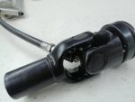
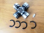
66111-46240 kit u-joint only, 2x 25x44 inside clip rings

o-ring king pin support to rear axle, 2x 50x3mm NBR shore 70
o-ring king pin support to knuckle bar, 2x 45x3mm NBR shore 70
o-ring king pin support to king pin, 2x 20x2.4mm NBR shore 70

I started by removing the paint with a CSD disk and then rounded off all sharp corners on all parts to improve paint thickness and hence get better corrosion protection.

IMG_20250409_155614.jpg

Followed by sand blasting and chemical rust removal.

IMG_20250410_105539.jpg IMG_20250410_110056.jpg IMG_20250410_202714.jpg

Then two thin layers of epoxy primer and top coat.

IMG_20250411_151403.jpg

The wheel bearings were in good condition, so I removed the seal disks, cleaned them thoroughly and applied new wheel bearing grease.

IMG_20250413_170732.jpg

I first thought the thrust bearings are worn because the knuckle arm was scraping on the king pin support. But when the new bearings from Kubota arrived they were exactly the same size and no wear visible on the king pin support. I did not like that and made shims with 0.15mm thickness, 2 each side to go above the thrust bearing creating a 0.3mm gap and no scraping any more.

IMG_20250414_153828.jpg

I got a set of nuts and bolts and washers from another tractor zinc electroplated and yellow passivated.

IMG_20250331_184247.jpg

So everything ready to be assembled.
 
Last edited:
  • Like
Reactions: 1 user

Hugo Habicht

Well-known member
Lifetime Member

Equipment
G1900
Jun 24, 2024
519
662
93
Ireland
Rear wheel steering assembly

Insert one clip ring into the axle support, slide in both wheel bearings and secure with the second clip ring.

IMG_20250413_190956.jpg

Insert wheel nut studs into the wheel hub. I turned them around with the longer part to the inside and secured them with counter nuts M10x1.25. This way the studs will not protrude the wheel nuts any more.

IMG_20250414_111233.jpg

Push in the wheel hub and secure with the clip ring on the inside. I had blackened the clip rings beforehand and applied corrosion protection wax over the clip rings.

IMG_20250414_111428.jpg

Insert the u-joint and secure with clip ring. I also replaced the grease nipples. The u-joint kits from Kubota were over $100 so I ordered some on the internet for under 10% of the Kubota price. I did not get them yet, so for the moment I painted the yokes and cleaned and greased the old u-joints, so they have to be replaced later.

IMG_20250414_131736.jpg IMG_20250414_131740.jpg


The drive shaft bearing is pushed into the king pin support and secured with the clip ring. I replaced one of the bearings that did not run smoothely after cleaning.

IMG_20250414_121852.jpg

Then the oil seal ring is pressed in.

IMG_20250414_124046.jpg

O-rings over the gear box side, into the groove around the thrust bearing and push in the knuckle bar and king pin plastic bushings.

IMG_20250414_124443.jpg IMG_20250414_124646.jpg IMG_20250414_124658.jpg
 
Last edited:
  • Like
Reactions: 1 user

Hugo Habicht

Well-known member
Lifetime Member

Equipment
G1900
Jun 24, 2024
519
662
93
Ireland
Rear wheel steering assembly (continued)

First we clean around the rear axle. Keep any dirt out, even tiny particles can cause damage to the hydraulic system.

IMG_20250414_151856.jpg

Then we apply grease to the o-ring and the seal ring of the king pin support and to the axle end and slide the support over the axle and into the rear axle. Careful not to damage the oil seal. Insert 4 bolts and tighten with 26Nm (19lbft).

Insert stud into bottom inside thread of axle support. This stud has two different thread sizes, the standard M10 is going into the support and the M10x1.25 fine thread sticking out is for the nut.

Now apply grease to the thrust bearing and apply grease generously to the bushings top and bottom. Insert the thrust bearing from the bottom, wide part up. It should stick in the grease. Now put small o-ring onto king pin support and slide axle support over king pin support. The drive shaft u-joint has to slide over the axle. Take care that the small o-ring is not squeezed.

Now feel the alignment with a finger and adust thrust bearing and o-ring if required. Insert king pin and knuckle arm. Insert bolts and spring ring and nut over the stud and tighten with 52Nm (38lbft).

IMG_20250414_155229.jpg IMG_20250414_155225.jpg IMG_20250414_155850.jpg

Right side is done same way.

IMG_20250414_164245.jpg

Apply grease to all grease nipples.

Attach tracking bar and tighten crown nuts and secure with split pin. Adjust tracking bar so that wheel hubs are parallel.

Attach wheels and steering bar. Adjust steering bar that all four wheels are parallel to the frame when steering wheel is in the middle.

IMG_20250414_165523.jpg IMG_20250414_183901.jpg

Fill up HST hydraulic fluid (see servicing earlier in this thread). Check for leaks and after a short drive check and correct HST fluid level.


Looks a bit better already with the wheels done.

IMG_20250414_183843.jpg


Technically the tractor is in order now apart from the steering box that is within specification but not good enough for my taste.

So replacing the floor panel that somebody chopped to bits to mount a cabin and restoring the panel parts is next.
 

Attachments

  • Like
Reactions: 3 users

Hugo Habicht

Well-known member
Lifetime Member

Equipment
G1900
Jun 24, 2024
519
662
93
Ireland
Wheel drive shaft u-joints

Kubota price of $102 for one of those is totally out of question. So I ordered a few of Nissan U-joints 25x44mm for 7 quid each. Arrived today and they fit.

They have a grease nipple in one of the needle bearings, so you need 3 u-joints swap that cap out. Or you simply glue in a piece of M6 thread.

A grease nipple won't fit in this position, so what I will do is drill a hole into the cross, cut a thread and put it in the centre.
 

Attachments

Last edited:
  • Like
Reactions: 1 user

nlefmann

New member

Equipment
L4150D
Jul 30, 2017
13
3
3
Aromas, Ca, USA
On mine for tacho I opened the alternator and traced the AC signal with my little pocket O/Scope. Once I had the proper square wave I soldered everything up. I'd LOVE to have an actual instrument panel like that though
Hi Lmichael I'm trying to get a tach signal out of a new alternator for my L4150 but not confident in making the right connection as you did. Any chance you took a picture of where you soldered the signal wire to obtain the square wave?
 

lmichael

Well-known member

Equipment
Kubota G2160
Apr 23, 2021
714
341
63
Rockford IL area
Sadly no. Actually I did not have to solder it. I simply took advantage of where the field coils (stator) hooks up with little lug connectors so I simply soldered one on and when I found my square wave I put the lead there. I didn't think at the time to document it all with photos. Now I wish I had.
However there are some other ways to get a signal. You can use a magnetic pickup and snag the pulse from the flywheel ring gear, or there are some magnetic pickups where you can get the pulse by strapping it to the alternator. Truth be told I may still go to a flywheel pickup. Not because the alternator one doesn't work or work reasonably well. But because I've got this weird obsession with "tinkering" and sometimes not leaving well enough alone :D
In any case no matter what you will need to get an optical tach to calibrate the electrical one.
The nice thing is an old school diesel (unlike a carbureted) gas engine will hold a very steady RPM. So I was able to run the optical up to a set speed (IIRC I used 2k rpm) and calibrated to that 2k reading. Then double checked throughout the range to make sure idle was 1100, on both and 1500, 2500 and so on. I just wish I was better at converting mm to inches as I ended up with far too big a tach :D Looks like a 60s muscle car
 

Russell King

Well-known member
Lifetime Member

Equipment
L185F, Modern Ag Competitor 4’ shredder, Rhino tiller, rear dirt scoop
Jun 17, 2012
6,170
1,896
113
Austin, Texas
@lmichael
just remember that 1 inch is 25.4 mm (or just use 25 if you don’t want an accurate measurement)

X inches * (25.4 mm/1 inch) = Y mm
Y mm * (1 inch/25.4 mm = X inches

To understand it somewhat as a general concept it is called “unit conversion” and you are just multiplying one unit times the number one BUT that is a specific set of numbers that are the right numbers and units.

You already do it in your head for inches and feet (or yards). 12 inches = 1 foot so you can use that as a “one” if you divide feet by inches or inches by feet.

It is one of the best tricks I learned from some teacher a long time ago. You can string the units you can remember together to get to the units you need!

25 inches is how many yards?
25 inches, 12 inches per foot, 3 feet per yard is what you can remember
so
25 inches * (1 foot/12 inches) * ( 1 yard/3 feet) = ?
written another way putting the numbers together and the units together is
(25/(12*3)) (inches/inches)(feet/feet) yard. (See the inches can be crossed out since it is 1 and so can the feet because anything divided by itself equals 1 (except 0/0!). That leaves yard as the unit!
So 25 inches = .69 yards

Sorry for the post since you can also just ask the internet now and your smart phone will give you the answer.
 
  • Like
Reactions: 1 user

TheOldHokie

Well-known member
Lifetime Member

Equipment
L3901/LA525, B7200DT/B1630, G2160/RCK60, G2460/RCK60
Apr 6, 2021
9,597
5,056
113
Myersville, MD
windyridgefarm.us
@lmichael
just remember that 1 inch is 25.4 mm (or just use 25 if you don’t want an accurate measurement)

X inches * (25.4 mm/1 inch) = Y mm
Y mm * (1 inch/25.4 mm = X inches

To understand it somewhat as a general concept it is called “unit conversion” and you are just multiplying one unit times the number one BUT that is a specific set of numbers that are the right numbers and units.

You already do it in your head for inches and feet (or yards). 12 inches = 1 foot so you can use that as a “one” if you divide feet by inches or inches by feet.

It is one of the best tricks I learned from some teacher a long time ago. You can string the units you can remember together to get to the units you need!

25 inches is how many yards?
25 inches, 12 inches per foot, 3 feet per yard is what you can remember
so
25 inches * (1 foot/12 inches) * ( 1 yard/3 feet) = ?
written another way putting the numbers together and the units together is
(25/(12*3)) (inches/inches)(feet/feet) yard. (See the inches can be crossed out since it is 1 and so can the feet because anything divided by itself equals 1 (except 0/0!). That leaves yard as the unit!
So 25 inches = .69 yards

Sorry for the post since you can also just ask the internet now and your smart phone will give you the answer.
My cheap Android phone will give me the answer without the internet and its more reliable than my arithmetic :rolleyes:

Dan
 
  • Like
Reactions: 1 user

lmichael

Well-known member

Equipment
Kubota G2160
Apr 23, 2021
714
341
63
Rockford IL area
I literally was just not paying attention when I bought it. I'm actually pretty well versed in metrics (actually prefer it to our US system or Imperial). I honestly wish we'd simply just drop the whole Imperial system here in the US and go over to metric. As the constant mix of the two drives me nuts
 
  • Like
Reactions: 1 users

nlefmann

New member

Equipment
L4150D
Jul 30, 2017
13
3
3
Aromas, Ca, USA
Hi Lmichael I'm trying to get a tach signal out of a new alternator for my L4150 but not confident in making the right connection as you did. Any chance you took a picture of where you soldered the signal wire to obtain the square wave?
Thanks for your reply. I actually tried a sensor on the flywheel with no joy. I adhered a magnet to the flywheel. AGREE ON THE SPEED SENSOR. I did get lucky there and found a free one for the iphone that seems to work very well.
 

Hugo Habicht

Well-known member
Lifetime Member

Equipment
G1900
Jun 24, 2024
519
662
93
Ireland
I actually tried a sensor on the flywheel with no joy. I adhered a magnet to the flywheel.
Post #39 ( Link post #39) in this thread shows a tacho sensor that works on the flywheel. Similar sensors are available off the shelf, I just wanted a smaller one (see picture) Passive automotive ABS sensors should work on the teeth too. Make sure your tacho can handle the frequency (4.6kHz at maximum engine speed), maybe that's why your sensor did not work.

If you glue a magnet onto the flywheel make sure to glue a second one (or piece of metal of same weight) onto the opposite side to keep it balanced.
 

Attachments

lmichael

Well-known member

Equipment
Kubota G2160
Apr 23, 2021
714
341
63
Rockford IL area
I would think the reluctance of the flywheel teeth going by should generate plenty of signal. If you think about it on FI vehicles where engine speed is important to be sensed for various operations that type of signal is all they use. No magnet glued anywhere
 
  • Like
Reactions: 1 user