correct but the knowledge is being shared which is important to those that need itJust a reminder --> THIS DISCUSSION WAS OVER IN 2017
Bad Dynamo?
- Thread starter CBH
- Start date
What you say above only holds true for AC voltage measured with a "True RMS" meter. Most folks do not have access to such a device. Instead, their AC meter may measure "Peak to Peak" voltage.you only need 10 VAC as the input to a full wave bridge to get 14 VDC
you need somewhat less than 20 VAC into a single diode to get 14.5 VDC
You can check out he original B&S patent dating to 1973 for the basis of all 'rectifier/regulators made since then and Byte Magazine for Steve Ciarcia's great article on how to build power supplies.
If I recall my electronics training (40 year ago) one must convert "Peak to Peak" voltage to "RMS" using mathematics.... otherwise, the numbers you posted are inaccurate.
Basic Power Supply Rectification Tutorial
Tutorial on power supply rectification. We examine several working examples with basic calculations.
www.bristolwatch.com
I guess what I am saying here is AC volts (peak-to-peak) CANNOT be rectified into MORE voltage DC. It is not mathematically possible.
Most equipment I work on will measure more like 20+ VAC out of the alternator/generator. Three-Phase units can be more complicated.
Last edited:
Just a few quick notes on a revived thread that is useful for people troubleshooting this part of the engine/tractor:
1. A little quick background, RMS stands for Root Mean Squared and is a mathematical conversion of the AC sine wave to a value that would produce the same power dissipation/heat in a perfect resistor as a DC source of the same value. Peak voltage is 1.41 x RMS and Peak to Peak is 2.82 x RMS.
In the U.S., nominal AC voltage at your household outlet is ~120 volts AC and this is the RMS value. Peak voltage from your AC outlet is 169.2 volt, peak to peak is the absolute difference between positive and negative peaks or 338.4 volts nominal.
2. The common DMM (digital multi-meters) that are available today are referred to as RMS and they will provide the RMS, not peak or peak to peak value, when measuring AC voltage.
As a minor distinction, the cheaper meters are not "true RMS" and will read slightly off on the somewhat to heavily distorted sine wave produced by some sources. The commercial power coming into your house will be a very pure sine wave and unless something in your home (i.e. light dimmers and SCR controlled space heaters) is causing distortion, a cheap DMM and a true RMS DMM will read identically (within the calibration tolerance of the two units) when measuring a clean sine wave. But a lot of AC sources don't produce a clean sine wave output (low cost 12 VDC to 120 VAC inverters, some portable generators) and a lower cost DMM will often read slightly high because of the distorted and dirty non-perfect sine wave produced by these units. For several years, I used a portable 10KW gas generator for power outages and it had a fairly dirty output compared to commercial but the 40KW diesel generator I installed has a very clean sine wave output.
3. When converting AC to DC via the typical full wave bridge rectifier, the output will be a series of pulses with the peak voltage of the pulse equal to just under the peak (NOT peak to peak) AC input from the source. The slight reduction from absolute peak is due to a very small voltage drop across the diodes in the bridge rectifier. So a dynamo with 20 VAC RMS output will produce slightly under 28 volt peak DC voltage pulses but the smoothed DC value under load would be less than that dropping to slightly under 20 volts at heavy load.
Or in short, the DC output voltage from a bridge rectifier in a heavily loaded circuit will be very close to the RMS AC voltage input to the bridge. Under light load it can increase to about 1.41 times the RMS AC input.
If the Kubota dynamo is producing a very high AC voltage under load, then it sounds like their vintage rectifier/regulator circuit is using a single diode half wave rectifier circuit which produces a useful output under heavy load of about .45 x AC input.
Hammond transformer company provides a nice design sheet for their transformers explaining expected output under different rectifier configurations and load conditions: http://www.hammondmfg.com/pdf/5c007.pdf
4. The output pulse repetition rate is double that of the AC input frequency with a full wave bridge rectifier (i.e. 60 hertz AC input results in 120 DC pulses per second at the output node of the bridge rectifier). This is important when you need to convert the AC to near pure DC because the capacitance value needed for filtering is reduced when fed with a higher pulse rate.
And one important caveat, especially with higher tech designs including your current car and truck BUT ALSO recent agricultural equipment built with a lot of sophisticated electronics. The equipment battery also serves as a filter and voltage surge limiter for the 12 volt power bus and you can create a lot of issues when "jumping" a defective battery in modern equipment.
A heavily discharged battery is fairly safe to "jump" but if you try to jump equipment with a defective battery (open cell or open interconnect between cells) or equipment where the starting fault is due to a defective battery cable or connector then the equipment battery no longer serves to absorb spikes that occur when connecting and disconnecting a jump pack, charger/starter, or other external source. This problem is greatly compounded by people who are nervous about jumping a vehicle and don't quickly and firmly attach the final negative lead between the external source and vehicle. When you are creating sparks when making that final connection, you are effectively connecting and disconnecting the external source at a rapid rate and this is what creates damaging voltage spikes. The best jump packs have a switch that allows you to make the connections and then turn the pack on, it avoids the issue of the nervous connecting operator.
Rodger
Nice write-up Roger
In my previous post, I tried to stay away from the math. Now that you have breeched that discussion.... I would like to mentions something else.
You discussed the calculations based on household A/C power and frequency. (60 CPS) Cycles Per Second
CPS is also known as HZ (Hertz)
BEWARE: The output frequency of dynamo is FAR above the 60 CPS of household power..... hence, the cheep AC meters you mentioned may be inaccurate due to the higher frequencies.
I have never measured it... but I am guessing that a belt-driven, 3-phase, dyanmo may have a frequency more than 8x of the engine RPM. (The belt spins the dynamo faster than the engine...and the dynamo has THREE pulses per revolution)
Suffice to say, the exact voltage readings may not matter... what matters is understanding the principals of operation so a diagnosis can be rendered.
Thanks Bruce and your comments about frequency of output and measurement accuracy are spot on! I would extend that further in that failing components in the rectifier/regulator assembly can cause it to exhibit unusual behavior over parts of the operating frequency range leading to proper function at high engine speed but out of spec behavior as engine speed and output frequency decrease.
Participants in these types of forums can gain an understanding of how things work making them able to repair assemblies at the component level instead of replacing the entire assembly which becomes increasingly important as tractors age and complete assemblies aren't available or become cost prohibitive. I spent several years in higher education on the way to a PhD but the most important thing I ever heard uttered in a classroom was from one of my undergrad profs who observed that when you memorize something, it is soon lost but if you understand it then you have it forever. Unfortunately in the service side of things, there isn't much understanding anymore by a lot of people in the field resulting in unnecessary expense and wasted time for the owner. Owners who understand and can repair their own stuff are far ahead.
I just finishing calibration of a Tektronix lab grade oscilloscope from the 1960s that had belonged to my father. The display (CRT) in the scope requires close to 10,000 volts on the accelerator helix to provide for a bright display and Tektronix used a very clever scheme to generate the required high voltage. It uses a RF (radio frequency) oscillator circuit operating at about 35 Khz (or 35,000 hz compared to the 60 hz standard line frequency) so both the transformer and filter capacitors are tiny compared to what would be needed for a line operated high voltage supply. This is similar to how modern switching power supplies work, they convert the low line frequency to RF in order to use tiny and cheap components making possible our tiny USB chargers and laptop power adapters.
A nice side effect of Tektronix using this oscillator type power supply is if something fails in the high voltage circuit, instead of smoke and fireworks the additional load just causes the oscillator to stop and output voltage immediately drops to 0. Because of the low value filter capacitors needed at this frequency, they don't store significant energy so they can't create any damage when the supply is shorted. Tektronix has provided many examples of smart engineering throughout their history.
And as a further side note, it is possible in fairly low current supplies to get higher DC output than peak to peak AC input because it uses several stacked rectifiers and filters. In the case of the classic Tektronix scope, three rectifier and filter sections were used as a voltage tripler to generate around 8,500 volts from an RMS input of around 1,300 volts and a fourth rectifier was used to provide a negative voltage output to another element of the CRT resulting in an absolute difference of 10,000 volts of electron accelerating potential with one element being held about 1,500 volts negative or "below ground". These voltage multiplier type circuits aren't terribly practical at higher current demands although voltage doubler circuits saw a fair amount of use while vacuum tubes were still being used in consumer electronics gear.
Rodger
One of the best examples of voltage doublers in modern computers is the MAX232 chip,now decades old. It used 'charge pumps' to generate the +12 and -12 volts from +5 needed for proper RS232 communications. lesser known is the 'cheat' to use a timer from a 3 volt microcomputer to generate +5 for the more common(cheaper) 5 volt LCD modules.
Jay,One of the best examples of voltage doublers in modern computers is the MAX232 chip,now decades old. It used 'charge pumps' to generate the +12 and -12 volts from +5 needed for proper RS232 communications. lesser known is the 'cheat' to use a timer from a 3 volt microcomputer to generate +5 for the more common(cheaper) 5 volt LCD modules.
But the old school dinosaur scopes with glowing vacuum tubes are far more cool than modern cold and soulless integrated circuits
This is my Tektronix 555 on its Tektronix Scopemobile. It is a true dual beam scope with two complete "gun" assemblies in its cathode ray tube. It has four plug in compartments for two time bases and two vertical amplifiers and with the plug ins in place it will have between 120 and 150 tubes in operation depending upon the specific plug ins used.
The power supply is external and combined weight is close to 120 pounds without the cart. The scope and its separate supply each has a large cooling fan and the system draws over a kilowatt from the power line in normal operation. It definitely wouldn't have gotten an energy star award but the build quality is gorgeous
I primarily use a pair of somewhat more modern Tektronix Type 7854 scopes on my bench but I have sentimental attachment to the type 555 and it still performs as it should.
Rodger
Man that's a NICE , REAL 'scope ! While I have some 'fancy', newer 'scope on the basement bench, I still use my young, 25 year old, B&K 20MHz on my 'lab' bench. Crazy thing is I have a R-C tester with 'magic eye' I power up once in awhile...
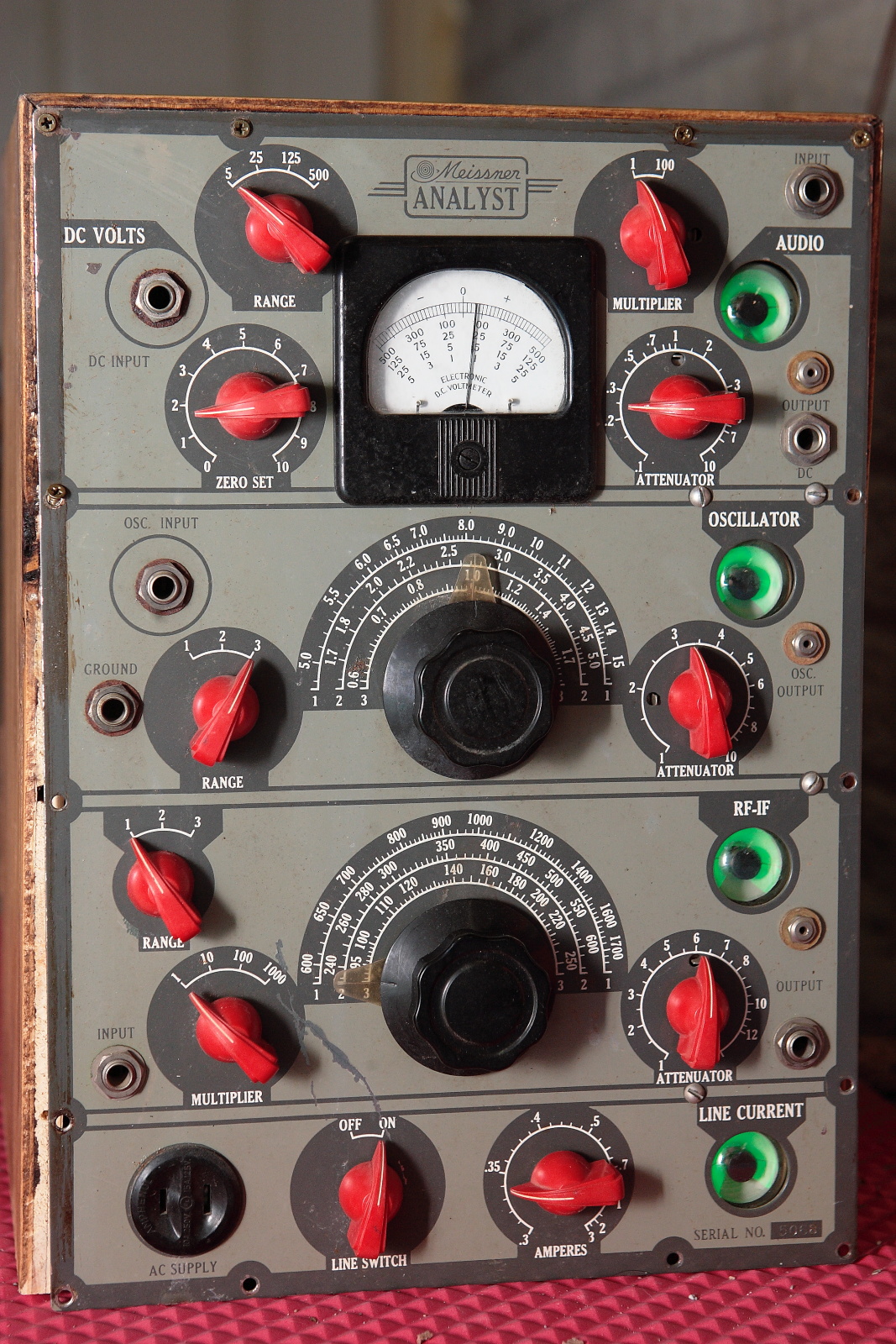
Thanks! Did you mention magic eye tubes? This is a Meissner Analyst from 1941. Test equipment from that pre-war era had style and some were styled to stand out on the service person's bench to show customers they were dealing with a well equipped professional
I picked this up at an antique mall for $10, I restored it electrically but haven't gotten around to the cosmetics yet. Pretty much useless these days compared to modern test equipment but it is eye catching.
Rodger
I picked this up at an antique mall for $10, I restored it electrically but haven't gotten around to the cosmetics yet. Pretty much useless these days compared to modern test equipment but it is eye catching.
Rodger
I wonder if this "electronics bench porn" is appropriate for OTT ? 

Who else watches the Utube electronics wizards?
Who else watches the Utube electronics wizards?