Hi all,
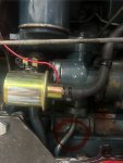
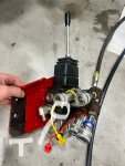
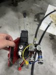
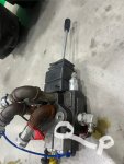
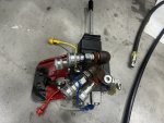
this is my first time posting on the forum and am looking to see if anyone has any insight on this. I have a grey market L2202-m 2 wheel drive tractor that I modified and bolted a TYM X25 loader attachment too, I’m trying to tap into the tractor pump/manifold for a pressure line and a return for the loader. There were two hard lines I removed with banjo bolts that are no longer used in the manifold and I installed fittings and hoses. The ports are labeled “PF” which is where I pulled supply and “EF” where I installed a return line. I have flow but doesn’t seem to have pressure, I adjusted both screws in front of manifold but no change. Does anyone know if what I’m doing is possible? The lift on the 3 point works well. Thanks!
Charles