The B2650 Project: Turbo Edition

TheOldHokie

Well-known member
Lifetime Member

Equipment
L3901/LA525, B7200DT/B1630, G2160/RCK60, G2460/RCK60
Apr 6, 2021
7,075
3,449
113
Myersville, MD
windyridgefarm.us
NOTE: YOU CAN'T INSERT AN NPT THREAD INTO A BSPT HOLE, BUT YOU CAN INSERT A BSPT FITTING INTO AN NPT HOLE! IT WILL JUST SEAT .
NOTE - You are mixing two incompatible thread forms with different flank angles, thread depths, and threads per inch and hoping to plug the resulting holes in the dike with sealant. Why beg for leaks?


Your metric fitting does not seal on the threads and does not need thread sealant. It is a face seal fitting and needs a sealing washer under the head.

9068.png


Dan
 
Last edited:
  • Like
Reactions: 1 user

Hahnsolo

Active member

Equipment
B2650 Tractor, B2782B Snow Blower
Mar 13, 2023
106
175
43
Rocky Mountains
Hi GrizBota:

I thought about the issue of rotation as well. I think I'll be Okay because the direction of rotation is tightening if it slips, plus, I honked it down pretty tight. Thanks for the comment.

Solo
 

Hahnsolo

Active member

Equipment
B2650 Tractor, B2782B Snow Blower
Mar 13, 2023
106
175
43
Rocky Mountains
Hi Dan, thanks for the comment.

The fitting I was referring to is the BSPT threads on the original oil pressure sender. Not sure what you are referring to with the metric fitting? The fitting that screws into the turbocharger oil inlet? Everything else is just 1/8"NPT threads on the distribution block. You may be right, it might leak, but I think I'm going to try it and see what happens. I'll report back if I find a problem. The odyssey continues. . .

Solo
 
  • Like
Reactions: 1 users

TheOldHokie

Well-known member
Lifetime Member

Equipment
L3901/LA525, B7200DT/B1630, G2160/RCK60, G2460/RCK60
Apr 6, 2021
7,075
3,449
113
Myersville, MD
windyridgefarm.us
Hi Dan, thanks for the comment.

The fitting I was referring to is the BSPT threads on the original oil pressure sender. Not sure what you are referring to with the metric fitting? The fitting that screws into the turbocharger oil inlet? Everything else is just 1/8"NPT threads on the distribution block. You may be right, it might leak, but I think I'm going to try it and see what happens. I'll report back if I find a problem. The odyssey continues. . .

Solo
I got the BSPT fittings confused but my comment about Incompatibility of BSPT and NPT is accurate. There are multiple important differences in the thread form. Don't try to jam them together with a wrench and sealant.

The thread sealant on the straight thread metric port adapter should definitely be cleaned off and then reinstalled with an appropriate sealing washer..

Just some friendly advice to help you avoid unnecessary problems down the line.

Dan
 
  • Like
Reactions: 1 user

Hahnsolo

Active member

Equipment
B2650 Tractor, B2782B Snow Blower
Mar 13, 2023
106
175
43
Rocky Mountains
Thanks Dan. Great advice. I think I will look into that. Always appreciate input from experienced readers. Edit: After doing some research I realized you were right. This fitting is not a tapered thread and relies on a copper or similar washer (which I didn't have) to seal between the turbo housing and fitting surface. I acquired a washer to use for this purpose and will detail this in future steps.

Solo
 
Last edited:
  • Like
Reactions: 1 user

GrizBota

Well-known member

Equipment
L3830HST/LA724, B2601/LA435/RCK54-32, RCR1872, CDI 66”grapple, pallet forks
Apr 26, 2023
1,142
727
113
Oregon
Hi GrizBota:

I thought about the issue of rotation as well. I think I'll be Okay because the direction of rotation is tightening if it slips, plus, I honked it down pretty tight. Thanks for the comment.

Solo
Thanks for the follow up. Sure, I follow your logic on the rotation, or loosing aspect. My comment was related the fitting itself cracking, as in a structural failure of the adapter due to millions of cycles of vibration with a relatively large mass hanging off of it. That’s what happened with the experience I related.

Thanks for the updates. As I mentioned, this is pretty interesting to me. I enjoy reading about the problem solving and discovery aspects. If it was a bolt up kit, well most anyone that can read, has the patience and attention to detail could do it (so now we’re down to between 1 and 5% of the general populace).
 

Hahnsolo

Active member

Equipment
B2650 Tractor, B2782B Snow Blower
Mar 13, 2023
106
175
43
Rocky Mountains
Ahh. . . gotcha. I missed the emphasis on the cracking. It's a very good point and a complete unknown. All I can do is run it and see what happens. I may need to find a way to support it in the future. Great comments from readers help refine the process.

And I would have to agree, this project is not for the faint of heart. There is so much time, money, research, and brain work that go into something like this. Hopefully it will all be worth it in the end.

Solo
 
  • Like
Reactions: 1 user

GrizBota

Well-known member

Equipment
L3830HST/LA724, B2601/LA435/RCK54-32, RCR1872, CDI 66”grapple, pallet forks
Apr 26, 2023
1,142
727
113
Oregon
Ahh. . . gotcha. I missed the emphasis on the cracking. It's a very good point and a complete unknown. All I can do is run it and see what happens. I may need to find a way to support it in the future. Great comments from readers help refine the process.

And I would have to agree, this project is not for the faint of heart. There is so much time, money, research, and brain work that go into something like this. Hopefully it will all be worth it in the end.

Solo
I’m sure it will be worth it.

What else are you going to do with your time and money (joke)? Using your brain, well that’s good regardless where you end up with the project.
 
  • Like
Reactions: 1 user

Jchonline

Well-known member
Lifetime Member

Equipment
Kubota L6060, KX040-4, M7060, RTV X1100C, M62 (sold)
Oct 28, 2018
1,388
598
113
Red Feather Lakes, CO
I am on the Eastern Slope, up in Red Feather Lakes.

Advice for your next purchase.....dont ever get a machine at over 7k without a turbo. I am at 9000 ft and all of my machines have turbo. The RTV X1100C originally did not, but it was a total lame turtle (even more so that it is at sea level) so I had one added. Its better...but still smokes some. The native turbo machines (L6060, KX040) have no issues. I purposefully purchased machines with turbos after my RTV problems. Altitude is no joke, and a turbo makes a huge difference.

Good luck with the addition and I really do hope it works out well for you. No you have me wondering if i should tune my RTV turbo and if that would reduce the smoking it does some times!
 
  • Like
Reactions: 1 user

Hahnsolo

Active member

Equipment
B2650 Tractor, B2782B Snow Blower
Mar 13, 2023
106
175
43
Rocky Mountains
Altitude is no joke, and a turbo makes a huge difference.
Boy, don't I know it. That's exactly why I'm even attempting this project. We had one of the worst winters on record this year, and even though my Kubota got through it, it struggled. If I can at least get back 3 or 4 pounds of boost, it will put me back to sea level (14.7 PSI), right now I'm at about 11 PSI at altitude. Anything beyond that is just a big bonus. I'm gonna find out, that's for sure.

If you are looking for some tuning advice, check out Rdrcr's post regarding his experience adding a turbo to his tractor. He has some great results posted and a really good description about how to adjust fuel to optimize performance.

See it here:


Solo
 
  • Like
Reactions: 1 users

Hahnsolo

Active member

Equipment
B2650 Tractor, B2782B Snow Blower
Mar 13, 2023
106
175
43
Rocky Mountains
My apologies for the long delay in posting the next steps. After looking at what I had decided to do with the oil supply and drain lines, I realized it was not optimum. This is one of the hardest parts of the build, due to the fact that there are so many ways to achieve the same thing with a plethora of different parts available, it becomes overwhelming. So, here is what I came up with. It is not the only way to do it, but it should work as intended. . .

The turbocharger (which had previously removed after test fitting to the exhaust manifold) was prepared as described below before being re-installed.

The hole size on the oil inlet of the turbocharger is a 10mm x 1.25 thread. I installed a 10mm x 1.25 by 4AN fitting with a copper sealing washer and snugged it down tightly with a wrench.
IMG_9767.jpg


DO NOT use thread sealant on this fitting, as the copper washer provides the seal, not the threads, which are not tapered.

IMG_9768.jpg


For the oil drain outlet, I had originally purchased a drain flange that had a 4AN fitting on the outlet. After more research I wasn't sure this would work, due to the small outlet hole in the center. I was concerned that it might be too restrictive and cause problems during operation. It is very difficult to find a drain flange for such a small turbocharger with the needed size and fitting, and this was the closest I could get to a reasonable solution. The flange had the required 38mm dimension between the mounting holes and included a mounting gasket and hardware. Unfortunately, the screws were 8mm instead of the 6mm needed for the turbo mounting holes. Back to the hardware store to get the proper 6mm-1.00x20 socket head screws, plus flat washers and lock washers. Drilling out the drain hole in the flange with a 1/4" drill bit should allow plenty of flow without restriction:

IMG_9779.jpg


I mounted the flange onto the turbo outlet utilizing the flange gasket and aforementioned hardware and snugged it down tight:

IMG_9780.jpg


Next, installation of the mounting studs into the new exhaust manifold were completed as follows using the part number acquired from Kubota:

Stud - Kubota P/N: 01513-70820 (qty.3)

When threading the studs into the exhaust manifold, caution must be exercised to prevent damage to the threads. One way to achieve this is to thread two hex nuts onto the long side of the stud and use two wrenches to snug them down very tightly. Once threaded into the mounting hole use a single wrench applied to the top nut to tighten the stud securely. After tightening, use two wrenches once again to break loose the two hex nuts and spin them off the stud.

(use anti-seize on studs screwed into flange):

IMG_9592.jpg
IMG_9594.jpg
IMG_9599.jpg


The turbocharger assembly with the inlet/outlet fittings attached was then re-installed onto the exhaust manifold with the proper gasket and the following hardware acquired from Kubota:

Turbo Flange Gasket -Kubota P/N: 16292-17100
Split Washer - Kubota P/N: 04512-70080 (qty.3)
Hex Nut - Kubota P/N: 02156-50080 (qty.3)

IMG_9649.jpg


With the turbocharger mounted securely to the exhaust manifold, the real fun begins. The oil inlet and outlet lines. . .

Solo
 

Attachments

Last edited:
  • Like
Reactions: 1 users

Hahnsolo

Active member

Equipment
B2650 Tractor, B2782B Snow Blower
Mar 13, 2023
106
175
43
Rocky Mountains
Probably the most critical part of any turbocharger installation is the lubrication system for the bearings that are exposed to extreme speeds and high heat. A failure in this system could spell the end of your turbocharger.

In researching information on the subject, I learned that proper sizing is an important aspect of the oil inlet and outlet tubing as described in the previous post.

For the inlet side, an 18" stainless steel braided oil feed line with one straight 4AN fitting and one right angle 4AN fitting was chosen for oil delivery. I installed it with the straight fitting attached to the distribution block, and the right angle fitting to the turbocharger:

IMG_9797.jpg


IMG_9788.jpg


As for the oil drain side, that was a whole 'nother can of worms. On the D1305 engine, there is a drain hole bored into the engine block on the left-hand side that can be used as an oil drain return from the turbo. I believe this was not just thrown in there by chance, but is actually designed specifically for that purpose. Anyway, this is a 0.470" diameter hole approximately 0.9" deep. This hole is located to the right and down from the oil pressure sender unit, and immediately to the right of the oil filter. On a normally asperated engine, there is a rubber plug installed to prevent oil leakage:

IMG_9603.jpg


I searched in vain to find an off-the-shelf fitting for this application and came up empty handed. It was then I realized I was going to have to machine a custom fitting. It sounds crazy, but this became an incredibly difficult task to figure out tubing type, tubing size, tubing length, and routing. As detailed in post #31, I had previously installed a 4AN oil drain fitting drilled out to 1/4" on the turbocharger oil drain outlet. Because of drainage flow concerns, I did not use the same type of 18" stainless steel braided hose used on the oil inlet. Instead, I discovered that a size 5/16" rubber fuel line would fit very snug over the threaded 4AN fitting on the drain flange. I bought a 24" length and literally threaded the tubing onto the fitting and left the other end hanging. Edit 1/1/24: After initial testing of the turbo, oil was found leaking from this fitting. A small hose clamp was added to the hose and tightened snuggly to prevent potential future leakage:

IMG_9790.jpg


One of the reasons I chose the 5/16" fuel line is that it would also fit on a 3/8" barbed fitting. I just so happened to have a stainless steel barbed fitting in the shop and realized it would be a good candidate for modification to fit down in the engine block hole.

The piece was turned down on a lathe to just under 0.047", and two O-ring slots were cut in to help provide a better seal. These are very deterministic measurements and I can only provide the concept for the drain fitting. You will have to adjust measurements based on your own fittings and hardware:

IMG_9711.jpg


I then stretched two thin O-rings over the fitting and into the grooves, resulting in a total outside diameter slightly larger than the fitting diameter. Again, this is dependent on the fittings and hardware available, but looks like this:

IMG_9713.jpg


The 5/16" fuel tubing that was left hanging down from the turbo drain was measured then cut to proper length experimentally and pushed onto the barbed fitting to complete the drain line: Edit 1/1/24: After initial testing of the turbo, oil was found leaking from this fitting. A small hose clamp was added to the hose and tightened snuggly to prevent potential future leakage:

IMG_9715.jpg


The rubber plug in the engine block hole was pried out with a screw driver and the fitting inserted. If properly machined, this part will slide nicely into the drain hole and have a very snug fit, preventing any oil leakage from the port and be held securely in the engine block:

IMG_9791.jpg


I chose to make this fitting out of stainless steel because that's what I had readily available to me. This part could also be manufactured by modifying one of many Nylon or Teflon fittings available through Grainger Industrial Supply (www.grainger.com) or similar supply house. The finished turbocharger mounting and oil lines should look something similar to this:

IMG_9786.jpg


Whew! That was one of the trickiest parts of the build. But now, I have to tackle one of the most challenging tasks of this project: Designing and building a new exhaust system. Stay tuned - the insanity continues. . .

Solo
 
Last edited:
  • Like
Reactions: 2 users

GrizBota

Well-known member

Equipment
L3830HST/LA724, B2601/LA435/RCK54-32, RCR1872, CDI 66”grapple, pallet forks
Apr 26, 2023
1,142
727
113
Oregon
Probably the most critical part of any turbocharger installation is the lubrication system for the bearings that are exposed to extreme speeds and high heat. A failure in this system could spell the end of your turbocharger.

In researching information on the subject, I learned that proper sizing is an important aspect of the oil inlet and outlet tubing as described in the previous post.

For the inlet side, an 18" stainless steel braided oil feed line with one straight 4AN fitting and one right angle 4AN fitting was chosen for oil delivery. I installed it with the straight fitting attached to the distribution block, and the right angle fitting to the turbocharger:

View attachment 111865

View attachment 111872

As for the oil drain side, that was a whole 'nother can of worms. On the D1305 engine, there is a drain hole bored into the engine block that can be used as an oil drain return from the turbo. I believe this was not just thrown in there by chance, but is actually designed specifically for that purpose. Anyway, this is a 0.470" diameter hole approximately 0.9" deep. This hole is located to the right and down from the oil pressure sender unit, and immediately to the right of the oil filter. On a normally asperated engine, there is a rubber plug installed to prevent oil leakage:

View attachment 111874

I searched in vain to find an off-the-shelf fitting for this application and came up empty handed. It was then I realized I was going to have to machine a custom fitting. It sounds crazy, but this became an incredibly difficult task to figure out tubing type, tubing size, tubing length, and routing. As detailed in post #31, I had previously installed a 4AN oil drain fitting drilled out to 1/4" to the turbocharger oil drain outlet. Because of drainage flow concerns, I did not use the same type of 18" stainless steel braided hose used on the oil inlet. Instead, I discovered that a size 5/16" rubber fuel line would fit very snug over the threaded 4AN fitting on the drain flange. I bought a 24" length and literally threaded the tubing onto the fitting and left the other end hanging:

View attachment 111875

One of the reasons I chose the 5/16" fuel line is that it would also fit on a 3/8" barbed fitting. I just so happened to have that fitting in the shop that I realized would be a good candidate for modification to fit down in the engine block hole.
The piece was turned down on a lathe to just under 0.047", and two O-ring slots were cut in to help provide a better seal. These are very deterministic measurements and I can only provide the concept for the drain fitting. You will have to adjust measurements based on your own fittings and hardware:

View attachment 111876

I then stretched two thin O-rings, over the fitting and into the grooves, resulting in an outside diameter slightly larger than the fitting diameter, again dependent on fittings and hardware:

View attachment 111877

The 5/16" fuel tubing that was left hanging down from the turbo drain was measured then cut to length experimentally and pushed onto the barbed fitting to complete the drain line:

View attachment 111878

If properly machined, this part will slide nicely into the drain hole and have a very snug fit, preventing any oil leakage from the port and hold it securely:

View attachment 111879

I chose to make this fitting out of stainless steel because that's what I had readily available to me. This part could also be manufactured by modifying one of many Nylon or Teflon fittings available through Grainger Industrial Supply (www.grainger.com) or similar supply house. The finished turbocharger mounting and oil lines should look something similar to this:

View attachment 111880

Whew! That was one of the trickiest parts of the build. But now, I have to tackle one of the most challenging tasks of this project: designing and building a new exhaust system. Stay tuned - the insanity continues. . .

Solo
Keep up the good work. I enjoy reading the updates. Thanks for sharing the trials as well.

So the return side of the oiling system must be low (er) pressure. Any idea what those pressures are? Is the inlet side around 15 psi?
 

Hahnsolo

Active member

Equipment
B2650 Tractor, B2782B Snow Blower
Mar 13, 2023
106
175
43
Rocky Mountains
Hi GrizBota:

To my knowledge, it's not that there is a difference between input and output, but that there is free flow from the outlet to prevent a potential backup of oil that could potentially lead to a pressure build up and cause the bearings to smoke. I don't really think it is much of a problem in a utility tractor turning 2500 RPM max, but could be in a high performance application running much higher engine RPM's.

At this point, I have no idea what the oil pressure will be going into the turbo. I will have to wait until I start testing everything and report back.

Solo
 
  • Like
Reactions: 1 user

Rdrcr

Well-known member
Lifetime Member

Equipment
L2501 w/ S2T Turbo Kit = 35 PTO HP (Current), B2601 (Sold)
May 7, 2021
633
658
93
WA
Great job on the oil drain block fitting! That’s a very nice piece! Better than my nylon fitting but, identical to what’s in my head if we decide to make a new fitting. I’m very impressed.

Looking forward to future updates!

Mike
 
  • Like
Reactions: 1 user

GrizBota

Well-known member

Equipment
L3830HST/LA724, B2601/LA435/RCK54-32, RCR1872, CDI 66”grapple, pallet forks
Apr 26, 2023
1,142
727
113
Oregon
Hi GrizBota:

To my knowledge, it's not that there is a difference between input and output, but that there is free flow from the outlet to prevent a potential backup of oil that could potentially lead to a pressure build up and cause the bearings to smoke. I don't really think it is much of a problem in a utility tractor turning 2500 RPM max, but could be in a high performance application running much higher engine RPM's.

At this point, I have no idea what the oil pressure will be going into the turbo. I will have to wait until I start testing everything and report back.

Solo
Ok. Thanks. Thinking about it, I agree, the pressure should be relatively similar though-out the system. It was the lack of a positive treaded connection that made me curious.

Sounds like your system is similar in concept to @Rdrcr and that system is working fine.
 

Hahnsolo

Active member

Equipment
B2650 Tractor, B2782B Snow Blower
Mar 13, 2023
106
175
43
Rocky Mountains
Ok. Thanks. Thinking about it, I agree, the pressure should be relatively similar though-out the system. It was the lack of a positive treaded connection that made me curious.

Sounds like your system is similar in concept to @Rdrcr and that system is working fine.
Yes, my system is similar to Mike's, so I have a high confidence that it will work well.

Solo
 
  • Like
Reactions: 1 users

Hahnsolo

Active member

Equipment
B2650 Tractor, B2782B Snow Blower
Mar 13, 2023
106
175
43
Rocky Mountains
As arduous as it was to configure and plumb the oil system for the turbocharger, it pales in comparison to what came next: The design and construction of the exhaust and compressor side plumbing systems.

There have been no new posts on this thread for 2 or 3 weeks for a reason. Simply stated, this involved creating and building pipe structures in 3D space while trying to avoid existing hoses, brackets, wire harnesses, an alternator, an AC compressor, and other obstacles not originally accounted for. Not to mention keeping the two different systems from interfering with each other, much like two entwined roller coasters at an amusement park.

I originally started designing and building the exhaust side first, as this seemed to be a natural progression of the project. What I found, however, changed the order of this part of the build for several reasons.

First, I realized that it would be counter-productive to try and route the exhaust piping where it needed to go without considering the location and routing of the compressor outlet from the turbo, which I could see was very close to where the proposed exhaust pipe routing would be.

Second, I really hadn't put much thought into WHAT type of air filter I was going to use for the inlet side, and WHERE I was actually going to mount it. The difficulty of building the exhaust system demanded answers before proceeding with the build.

Therefore, to streamline the process and hopefully prevent frustration to anyone who might attempt a similar project, I will detail the fresh air / compressor side construction and installation first, then the exhaust side.

I had already stripped out the original air filter, hose, and exhaust pipes from the engine compartment, and was now faced with the dilemma of what to do next. Looking at the original location of the air filter, I tried to figure a way to leave it in that position and just use extra hose to route to/from the turbo charger. After all, there was a handy U-shaped bracket that the air filter snapped into that would simplify things, but would really be awkward and inefficient for routing and just add unwanted length and bends to the system.

In a flash of inspiration I realized that I could relocate the air filter directly above the turbocharger by mounting the end cap to the firewall. I sanded the back of the cap so it would fit flat against the firewall and drilled two holes to secure it with rivets. Note the orientation of the end cap with the drip fitting facing straight down to allow water to drain if needed. It is also necessary to mount the end cap high on the firewall for clearance to the turbocharger, but also to provide enough clearance to prevent the top of the hood from interfering with the air filter when closed:

image3 (1).jpeg


But the real coup de grâce was achieved by positioning the front half of the air filter with the air inlet facing downward at ~ 30 degrees. This is achieved by rotating the front half of the air filter and aligning the end cap with the original latches. By re-purposing the original plastic air inlet manifold by trimming it to fit close, it created the perfect air inlet pipe to the air filter:

image1 (4).jpeg


The air filter and inlet pipe assembly was then installed on the end cap and measured to determine where to cut off the excess pipe:

image4 (1).jpeg


After trimming, this put the end of the air inlet pipe within about 1/2" from the left side grill of the hood when closed, allowing the air filter to draw fresh air in directly through a very short 1-3/4" pipe with very little air resistance. Closing the hood and observing exactly where the pipe was positioned revealed that the top edge was a little bit high, so by using a heat gun I was able to reshape the inlet to maximize airflow into the air filter:

image6 (1).jpeg


Re-installing and checking air inlet pipe alignment verified perfect positioning behind the grill:

image8.jpeg


This whole process actually came together quite quickly when I finally figured out where exactly to mount the airbox. Oh, BTW, I also installed a new filter element to start off on the right foot. The old one was looking pretty gnarly.

So that's it for now. Next post I'll detail the plumbing from the outlet of the airbox into the turbocharger, and from the outlet (compressor) side of the turbocharger to the air intake manifold of the engine. Stay tuned!

Edit 10/15/23: I was originally going to detail the remainder of the air filter plumbing on another post, but decided it made more sense to finish it in this one.

With the air filter firmly mounted and the inlet side complete, it was time to figure out how to connect the outlet side to the turbocharger. By positioning the air filter where I did, it positioned it in such a way that I could simply re-purpose the original rubber hose for connection to the turbocharger inlet.

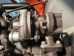
The air filter side was simple, since it was connected to the 1-3/4" outlet originally. Fitting the turbocharger inlet side was more challenging. I was going to use a reducer hose to step the tubing size down to accommodate the 1-1/4" inlet, but realized I wouldn't have enough room (imagine that). After thinking about it a bit, I realized I could cut a section of scrap hose down to fit around the neck of the turbo inlet fitting, which would fit perfectly inside the hose from the air filter.

image5 (3).jpeg


It took several tries to determine how long to make the rubber piece to fit around the neck of the inlet, but I finally got it fitting perfectly:

image6 (2).jpeg


I then removed the rubber piece and stuffed it into the tubing coming down from the air filter:

image7 (1).jpeg


I left a small amount of the rubber sticking out of the hose to allow it to slide in a bit when fitted to the inlet:

image8 (1).jpeg


Finally, by using 2" diameter hose clamps, I was able to get a good tight seal on both ends of the hose with a U-shaped connection between the air filter and turbocharger:

image12 (1).jpeg


This looks a little silly on the turbo side, but actually provides a really simple, non-restrictive connection that cost nothing to implement.

Ok, NOW the compressor inlet side of the turbo is complete, it's time to focus on the outlet side to the engine air manifold. That's coming up next...

Solo
 
Last edited:
  • Like
Reactions: 4 users

Rdrcr

Well-known member
Lifetime Member

Equipment
L2501 w/ S2T Turbo Kit = 35 PTO HP (Current), B2601 (Sold)
May 7, 2021
633
658
93
WA
^^^^
It certainly takes some time and thoughtful planning to get the Turbo pipes fabricated properly to delivery optimum performance. I'm glad you're detailing the difficulty and time spent to get it done right.

Question/Suggestion: The Turbocharger is going to generate heat. Are you planning on fabricating a heatshield to go between the Turbo and the air cleaner assembly to deflect some of that heat?

Mike