A hell of a ride boys! And if I was a betting man, I would bet somebody from the big "K" has been following along. Guys like you make me sit back in awe and shake my head,, ya done good! Now le see the bytch run !!!!!
The B2650 Project: Turbo Edition
- Thread starter Hahnsolo
- Start date

leveraddict
Well-known member
Equipment
2017 BX23S 60" LP BoxBlade 54" mower 60" BackBlade EA 12" 1 bottom plow & Forks
Interesting thread for sure! Im always amazed at the skills others have and what they can do! I am a shadetree mechanic and can just do the basic maintenance on these tractors. So this thread brings me to the question...what is the advantage of having the turbo upgrade? The hydraulic pump regulates FEL lifting and BH digging force so the turbo is no help there or is it? Maybe some extra pulling power is my guess if your into dragging logs out of the woods? I just dont know what the advantage is with the turbo? So what are the fruits of your labor?^^^^
That's no spoiler to me, lol.
I had my Turbo system installed and operating for a least a month before I began posting my thread. I would just work on each chapter and then release it once I was finished. I enjoy writing but, it takes me quite some time to produce the content in my thread. It's been a fun journey and I really really have enjoyed the fruits of my labors. There's nothing like having that additional power supplied by Turbocharger.
Mike
LOL, thanks skeets. Stay tuned, there's more insanity to come!A hell of a ride boys! And if I was a betting man, I would bet somebody from the big "K" has been following along. Guys like you make me sit back in awe and shake my head,, ya done good! Now le see the bytch run !!!!!
Solo
Hi leveraddict:
Thanks for the post. Good question.
In the first few posts on this thread, I describe the environment I live in and the impetus for adding a turbo to my tractor. The bottom line is the loss of power associated with an increase in altitude. I live at just under 8000' in the Rockies, which equates to a power loss of approximately 24% (3% per 1000'). With the amount of snow we receive each year, that's a hell of a hit. Believe me, if it wasn't necessary I wouldn't put myself through this insanity. All-in-all though, It's been an amazing experience and I have gained a whole lot of knowledge. Also, if I can inspire others to attempt there own builds, it will be worth it. Thanks for reading.
Solo
The Turbo will not increase FEL lifting capacity or BH digging force.Interesting thread for sure! Im always amazed at the skills others have and what they can do! I am a shadetree mechanic and can just do the basic maintenance on these tractors. So this thread brings me to the question...what is the advantage of having the turbo upgrade? The hydraulic pump regulates FEL lifting and BH digging force so the turbo is no help there or is it? Maybe some extra pulling power is my guess if your into dragging logs out of the woods? I just dont know what the advantage is with the turbo? So what are the fruits of your labor?
However, the Turbo will provide more power for running and driving PTO powered implements and machinery like rotary cutters, snowblowers, flail mowers, finish mowers, rotary tillers, etc in demanding conditions and/or challenging terrain. More power for pulling larger, heavier dirt working ground engagement implements at higher operating speeds. More power for traversing steep terrain. More power for larger PTO powered implements like wood chippers, PTO generators, post hole diggers, etc. More power for High Altitude operation…an extremely important option for those living in high elevations! Plus, a significant cost savings when compared to alternative Kubota tractor options within its class size and an overall less expensive overall investment.
Mike
Alright, you guys ready for some pain? Here we go; the exhaust pipe fabrication. . .
In my previous over-wordy post about steel, I outlined the pros and cons of stainless versus mild steel. Personally, I chose stainless steel for it's advantages and longevity, and just accepted it's cost difference and fabrication difficulties as being worth it.
Also, if you read this thread from the beginning, you will note that I also chose to purchase a new factory exhaust manifold with a 3-hole flange that perfectly aligned with the 3-hole flange on the turbocharger. This cost a little more money but eliminated the need to weld up an adapter flange that converted the 4-hole flange on the original exhaust manifold to the 3-hole flange. (Note: Kinugawa offers a 2-piece flange kit if you wish to go with the adapter method, HOWEVER, it is made from mild steel and will commit the rest of your exhaust pipe to mild steel for the reasons stated in the previous build post. You can still fabricate the exact same thing from stainless steel, but will take more time and effort. See https://shopping.kinugawaturbo.com/turbogasketflangemitsubishikubotatd025m-3ctd025m-5ctd025l-3c.aspx).
Either method is viable, however, if you chose the adaptor method, it will differ significantly from what I present here and require much more brain time to figure out the pipe routing differences. The techniques and general information presented, however, can be applied to either method.
Once you decide on the turbo mounting method and the type of steel, it all begins at the exhaust output of the turbocharger. I searched in vain for an of-the-shelf exhaust flange, and even went as far as ordering what I thought was the correct one from Kubota, only to find it was too big. So, instead, I worked with a CAD guy and transformed raw measurements into a Solid Works file that could be loaded into a CNC machine for manufacturing (I will make this file available for free to anyone who requests it). Machining mild steel is relatively straightforward. Machining stainless steel is an entirely different beast due to it's hardness and requires an experienced machinist who understands set up for cutting speeds and depth of cut. Otherwise, you will blow through a lot of really expensive end mills.
The exhaust flange should be fabricated from 1/4" to 3/8" material, due to the heat and stress of the application.
My original attempt at routing the exhaust pipe out of the turbo was laughably ridiculous. Somehow I got it in my head that I needed 2.5" pipe for this application. So I ordered a kit of numerous types and shapes of fittings and straight pipe. When I received it and opened the box, I realized what a HUGE mistake I made. There was absolutely no way in HELL I could route that pipe anywhere in that engine compartment, let alone the turbo. So, off I went, returning the misfit kit and ordering a bunch of individual 2" pieces consisting of 90's, 45's, and straight pipe.
While this was better, there still was not enough room between the face of the exhaust flange to the back of the firewall (exactly 4") to accommodate the 2" diameter pipe fittings. Success was achieved only when I stepped down to 1-1/2" diameter fittings coming out of the turbocharger. This alleviated two problems that made it impossible to accomplish any other way.
First, of course, was the radius of the 90° fittings provided enough room to route the pipe away from the flange and miss the firewall by 1/2". Cool.
Second, the mounting holes on the turbo exhaust flange are impossibly close to the 1-1/2" pipe that is welded as a spacer on the flange outlet. There is no room to weld this short spacer piece on the outside of the flange due to interference with the mounting holes, as seen below:
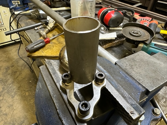
The only way to make this configuration work is to place the spacer pipe directly over the outlet hole, then weld it from the inside. Note the 8mm socket head screws shown for reference. They were chosen specifically for their small head diameter. Hex head bolts would not have worked here. Also, the wide opening in the flange was due to the change in material size. Once I went with 1-1/2" pipe, I didn't need the cut out.
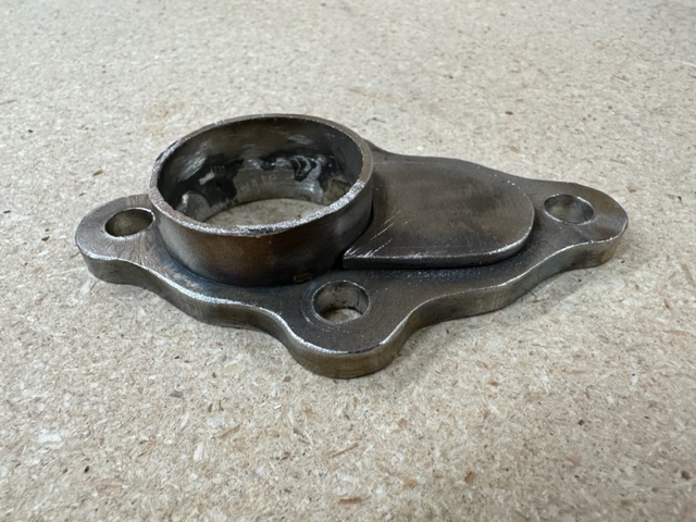
A small cover was fabricated for the cut out, and the spacer pipe was cut down to approximately 1/2" length. It may seem silly at first to cut this piece down so much, however, this piece is critical to allow access to one of the bolts during assembly. This will be detailed later. Here is the finished flange assembly:
With this critical piece complete, the real work can begin. The turbocharger was mounted in place on the new 3-hole exhaust manifold with the appropriate gasket and hardware finger tight, and the new exhaust flange also mounted finger tight to the turbocharger, with it's gasket.
Here's a little trick I discovered along the way that will make fabricating easier...
Originally, I would hold two pieces of pipe together with one hand, then wrap strips of gorilla tape around them with the other to hold them in place. This worked marginally well at first, but after attaching several pieces together, physics would take over and things would start slipping out of position. This was untenable.
Then an idea hit me: Hose clamps. Stainless steel hose clamps that you can buy in any big box or auto parts store. I bought 10 or so of 1-1/2" and 2" sizes and gave it a shot. Wow! What a difference! I could wrap a clamp between two adjacent pieces and cinch it down with a socket wrench, providing a fairly strong clamping force to hold the two parts together. I found that they could still be wrenched apart if you move them too much, but would hold everything together long enough to get a completed assembly out of the tractor and to the welder. This allowed for test fitting of different parts while routing the pipe. The remainder of the fabrication was completed with these clamps.
So the obvious question is: Ok, wise guy, how do you weld the pipes together without removing the clamps? Here's the cool thing. . . you can tack weld a few spots on each clamp right through the small slots on the clamp. The weld holds securely, then the rest of the clamp is snapped or ground off. The assembly can then be re-fitted into the tractor and checked for alignment. If there is a problem, the tack welds can easily be ground off the offending part, re-aligned, and the process repeated. It is best to construct the entire exhaust pipe in this manner, before final welding.
Before beginning, however, there is one thing that needs to be done. There is a small bracket with a hole in it attached to the back of the engine near the firewall. I believe this was used during manufacturing as a hardpoint to drop the engine into the engine compartment with a hoist or crane. It is not needed now and will interfere with the fitment of the new exhaust pipe. This is shown below and is fastened to the engine block with a singe bolt, which can be removed from the right side of the engine with an open-end wrench (see lower half of second picture). Remove this flange and bolt before proceeding with the build:
The first step is the attachment of two 1-1/2" diameter 90° sections to the turbo exhaust flange with a small spacer between them. This is the most critical section, as it allows space to clear the firewall and sets a critical angle and distance for the rest of the exhaust pipe. This is best represented by a picture:
It's somewhat difficult to see the small spacer between the two 90° fittings, but the two clamps hold it firmly in place. This spacer is a little tricky to size, but is somewhere between 1/2" and 3/4" long. It sets the distance for the first straight pipe section to fit between the turbo outlet fitting and radiator hose as shown below. (disregard the tack welds on the 45° fitting and bell adapter at this point, as they are only for reference):
After that critical alignment is set, the 45° fitting and 1-1/2" to 2" bell adapter is added to transition the remainder of the exhaust pipe to 2" diameter to improve exhaust flow. The 1-1/2" section of the exhaust pipe is shown in the following pic. Note the upward angle as it leads away from the second 90° elbow. The trick is to adjust the angle to keep the straight pipe low enough at the front to give clearance for the tubing that will exit the turbo air outlet, yet not run into the engine block at the rear:
The completed assembly will look similar to the following pic. At this point it is best to very carefully unbolt the assembly from the turbocharger so as not to upset alignment, then tack weld the four clamps shown on the right side. Do not weld the 45° fitting and bell adapter at this time as they will be adjusted in the next few steps.
This is probably a good place to stop for now. Don't want to burn anybody (or me) out. The next post will bring everything together and successfully route the exhaust pipe out of the engine compartment. 'Til next time; good night everybody.
Solo
In my previous over-wordy post about steel, I outlined the pros and cons of stainless versus mild steel. Personally, I chose stainless steel for it's advantages and longevity, and just accepted it's cost difference and fabrication difficulties as being worth it.
Also, if you read this thread from the beginning, you will note that I also chose to purchase a new factory exhaust manifold with a 3-hole flange that perfectly aligned with the 3-hole flange on the turbocharger. This cost a little more money but eliminated the need to weld up an adapter flange that converted the 4-hole flange on the original exhaust manifold to the 3-hole flange. (Note: Kinugawa offers a 2-piece flange kit if you wish to go with the adapter method, HOWEVER, it is made from mild steel and will commit the rest of your exhaust pipe to mild steel for the reasons stated in the previous build post. You can still fabricate the exact same thing from stainless steel, but will take more time and effort. See https://shopping.kinugawaturbo.com/turbogasketflangemitsubishikubotatd025m-3ctd025m-5ctd025l-3c.aspx).
Either method is viable, however, if you chose the adaptor method, it will differ significantly from what I present here and require much more brain time to figure out the pipe routing differences. The techniques and general information presented, however, can be applied to either method.
Once you decide on the turbo mounting method and the type of steel, it all begins at the exhaust output of the turbocharger. I searched in vain for an of-the-shelf exhaust flange, and even went as far as ordering what I thought was the correct one from Kubota, only to find it was too big. So, instead, I worked with a CAD guy and transformed raw measurements into a Solid Works file that could be loaded into a CNC machine for manufacturing (I will make this file available for free to anyone who requests it). Machining mild steel is relatively straightforward. Machining stainless steel is an entirely different beast due to it's hardness and requires an experienced machinist who understands set up for cutting speeds and depth of cut. Otherwise, you will blow through a lot of really expensive end mills.
The exhaust flange should be fabricated from 1/4" to 3/8" material, due to the heat and stress of the application.
My original attempt at routing the exhaust pipe out of the turbo was laughably ridiculous. Somehow I got it in my head that I needed 2.5" pipe for this application. So I ordered a kit of numerous types and shapes of fittings and straight pipe. When I received it and opened the box, I realized what a HUGE mistake I made. There was absolutely no way in HELL I could route that pipe anywhere in that engine compartment, let alone the turbo. So, off I went, returning the misfit kit and ordering a bunch of individual 2" pieces consisting of 90's, 45's, and straight pipe.
While this was better, there still was not enough room between the face of the exhaust flange to the back of the firewall (exactly 4") to accommodate the 2" diameter pipe fittings. Success was achieved only when I stepped down to 1-1/2" diameter fittings coming out of the turbocharger. This alleviated two problems that made it impossible to accomplish any other way.
First, of course, was the radius of the 90° fittings provided enough room to route the pipe away from the flange and miss the firewall by 1/2". Cool.
Second, the mounting holes on the turbo exhaust flange are impossibly close to the 1-1/2" pipe that is welded as a spacer on the flange outlet. There is no room to weld this short spacer piece on the outside of the flange due to interference with the mounting holes, as seen below:
The only way to make this configuration work is to place the spacer pipe directly over the outlet hole, then weld it from the inside. Note the 8mm socket head screws shown for reference. They were chosen specifically for their small head diameter. Hex head bolts would not have worked here. Also, the wide opening in the flange was due to the change in material size. Once I went with 1-1/2" pipe, I didn't need the cut out.
A small cover was fabricated for the cut out, and the spacer pipe was cut down to approximately 1/2" length. It may seem silly at first to cut this piece down so much, however, this piece is critical to allow access to one of the bolts during assembly. This will be detailed later. Here is the finished flange assembly:
With this critical piece complete, the real work can begin. The turbocharger was mounted in place on the new 3-hole exhaust manifold with the appropriate gasket and hardware finger tight, and the new exhaust flange also mounted finger tight to the turbocharger, with it's gasket.
Here's a little trick I discovered along the way that will make fabricating easier...
Originally, I would hold two pieces of pipe together with one hand, then wrap strips of gorilla tape around them with the other to hold them in place. This worked marginally well at first, but after attaching several pieces together, physics would take over and things would start slipping out of position. This was untenable.
Then an idea hit me: Hose clamps. Stainless steel hose clamps that you can buy in any big box or auto parts store. I bought 10 or so of 1-1/2" and 2" sizes and gave it a shot. Wow! What a difference! I could wrap a clamp between two adjacent pieces and cinch it down with a socket wrench, providing a fairly strong clamping force to hold the two parts together. I found that they could still be wrenched apart if you move them too much, but would hold everything together long enough to get a completed assembly out of the tractor and to the welder. This allowed for test fitting of different parts while routing the pipe. The remainder of the fabrication was completed with these clamps.
So the obvious question is: Ok, wise guy, how do you weld the pipes together without removing the clamps? Here's the cool thing. . . you can tack weld a few spots on each clamp right through the small slots on the clamp. The weld holds securely, then the rest of the clamp is snapped or ground off. The assembly can then be re-fitted into the tractor and checked for alignment. If there is a problem, the tack welds can easily be ground off the offending part, re-aligned, and the process repeated. It is best to construct the entire exhaust pipe in this manner, before final welding.
Before beginning, however, there is one thing that needs to be done. There is a small bracket with a hole in it attached to the back of the engine near the firewall. I believe this was used during manufacturing as a hardpoint to drop the engine into the engine compartment with a hoist or crane. It is not needed now and will interfere with the fitment of the new exhaust pipe. This is shown below and is fastened to the engine block with a singe bolt, which can be removed from the right side of the engine with an open-end wrench (see lower half of second picture). Remove this flange and bolt before proceeding with the build:
The first step is the attachment of two 1-1/2" diameter 90° sections to the turbo exhaust flange with a small spacer between them. This is the most critical section, as it allows space to clear the firewall and sets a critical angle and distance for the rest of the exhaust pipe. This is best represented by a picture:
It's somewhat difficult to see the small spacer between the two 90° fittings, but the two clamps hold it firmly in place. This spacer is a little tricky to size, but is somewhere between 1/2" and 3/4" long. It sets the distance for the first straight pipe section to fit between the turbo outlet fitting and radiator hose as shown below. (disregard the tack welds on the 45° fitting and bell adapter at this point, as they are only for reference):
After that critical alignment is set, the 45° fitting and 1-1/2" to 2" bell adapter is added to transition the remainder of the exhaust pipe to 2" diameter to improve exhaust flow. The 1-1/2" section of the exhaust pipe is shown in the following pic. Note the upward angle as it leads away from the second 90° elbow. The trick is to adjust the angle to keep the straight pipe low enough at the front to give clearance for the tubing that will exit the turbo air outlet, yet not run into the engine block at the rear:
The completed assembly will look similar to the following pic. At this point it is best to very carefully unbolt the assembly from the turbocharger so as not to upset alignment, then tack weld the four clamps shown on the right side. Do not weld the 45° fitting and bell adapter at this time as they will be adjusted in the next few steps.
This is probably a good place to stop for now. Don't want to burn anybody (or me) out. The next post will bring everything together and successfully route the exhaust pipe out of the engine compartment. 'Til next time; good night everybody.
Solo
Last edited:
Ok, It's been a long difficult push, so lets get the exhaust pipe finished up and routed out of the engine compartment.
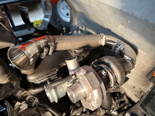
In the last build post, the 1-1/2" J-shaped header pipe was clamped together and removed from the turbocharger to be tack welded. After completing this task, the header pipe is re-installed onto the turbocharger with its gasket and held in place using the 8mm socket head bolts hand tightened to the flange. If fabricated correctly, it should look something like this when viewed from the top down:
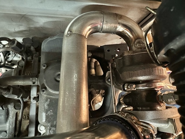
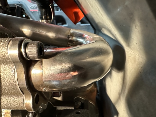
It is now very obvious why this pipe needs to be 1-1/2" diameter. Also critical is the use of tight radius 90° elbows to make the tight curve to the left and clear the firewall as seen in this side view:
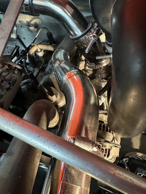
With the header pipe in place, the second half of the exhaust pipe (the down pipe) is fabricated and the joints clamped to hold them in place during fabrication. The bell adapter on the end of the header pipe is where the transition to 2" pipe occurs. From this point forward, all fittings and pipe will be 2" diameter.
The first piece to attach to the adapter is a 45° fitting that has been cut very close to the bend. The close cut is required to position the pipe between the radiator hose and the U-shaped air inlet tube on the turbocharger. The picture shows a tack weld, but disregard that and use a 2" clamp lightly snugged to hold the two pieces together for now:
At this point in the process, it is actually easier to stop working from the top-side down and start working from the bottom-side up. Let me explain. . .
There is a highly critical group of fittings that MUST be cut and fit precisely where the down pipe transitions from a horizontal to a vertical orientation in order to allow for spacing and clearance to heat sensitive components. Trying to add one fitting to another in a series from the top down can lead to cumulative errors and is just too difficult to achieve in this process. Therefore, fabricating and attaching the the vertical down pipe section is completed now.
This begins with the original mounting flange near the bottom of the frame that held the original exhaust pipe in a similar fashion. The original pipe was removed along with the bolt, leaving just a hole in the flange:
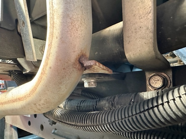
A new vertical down pipe was fabricated using a 90° elbow and a straight piece of pipe, which were welded together immediately, since positioning was not critical. A new mounting flange was fabricated and welded in place on the elbow near the bend. Although the picture shows mounting hardware attached to the pipe flange, disregard it, as no hole has been drilled in the flange yet:
Before drilling a new hole in the pipe flange and mounting the assembly to the frame, it is critical to position the new assembly to provide clearance around the front and two sides due to heat. The lower left-side plastic grill is temporarily re-attached finger tight, and the down pipe is lowered in place, with the new flange resting on top of the original frame mounting flange near the bottom:
The pipe needs to miss the plastic grill assembly by 1/2" to 3/4" on the left side:

And miss the radiator shroud on the right side and front side by the same amount:
With the exhaust end of the down pipe facing straight forward and the above criteria met, a Sharpie pen is used (from the bottom side) to transfer the lower frame mounting hole to the new mounting flange on the down pipe. The pipe is removed and the new mounting hole is drilled in the flange, after which, the pipe is lowered back down into its previous position and new mounting hardware is inserted and finger-tightened:
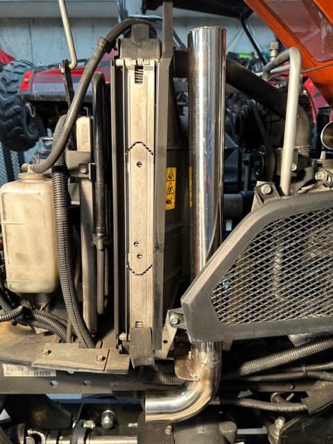
When finished, the down pipe assembly should look like this when installed:
Well, unfortunately, there is a 10 picture limit on any new post, and I have just about reached that limit. So for now we'll call it a day and have a cold one. Stay tuned. . .
Solo
In the last build post, the 1-1/2" J-shaped header pipe was clamped together and removed from the turbocharger to be tack welded. After completing this task, the header pipe is re-installed onto the turbocharger with its gasket and held in place using the 8mm socket head bolts hand tightened to the flange. If fabricated correctly, it should look something like this when viewed from the top down:
It is now very obvious why this pipe needs to be 1-1/2" diameter. Also critical is the use of tight radius 90° elbows to make the tight curve to the left and clear the firewall as seen in this side view:
With the header pipe in place, the second half of the exhaust pipe (the down pipe) is fabricated and the joints clamped to hold them in place during fabrication. The bell adapter on the end of the header pipe is where the transition to 2" pipe occurs. From this point forward, all fittings and pipe will be 2" diameter.
The first piece to attach to the adapter is a 45° fitting that has been cut very close to the bend. The close cut is required to position the pipe between the radiator hose and the U-shaped air inlet tube on the turbocharger. The picture shows a tack weld, but disregard that and use a 2" clamp lightly snugged to hold the two pieces together for now:
At this point in the process, it is actually easier to stop working from the top-side down and start working from the bottom-side up. Let me explain. . .
There is a highly critical group of fittings that MUST be cut and fit precisely where the down pipe transitions from a horizontal to a vertical orientation in order to allow for spacing and clearance to heat sensitive components. Trying to add one fitting to another in a series from the top down can lead to cumulative errors and is just too difficult to achieve in this process. Therefore, fabricating and attaching the the vertical down pipe section is completed now.
This begins with the original mounting flange near the bottom of the frame that held the original exhaust pipe in a similar fashion. The original pipe was removed along with the bolt, leaving just a hole in the flange:
A new vertical down pipe was fabricated using a 90° elbow and a straight piece of pipe, which were welded together immediately, since positioning was not critical. A new mounting flange was fabricated and welded in place on the elbow near the bend. Although the picture shows mounting hardware attached to the pipe flange, disregard it, as no hole has been drilled in the flange yet:
Before drilling a new hole in the pipe flange and mounting the assembly to the frame, it is critical to position the new assembly to provide clearance around the front and two sides due to heat. The lower left-side plastic grill is temporarily re-attached finger tight, and the down pipe is lowered in place, with the new flange resting on top of the original frame mounting flange near the bottom:
The pipe needs to miss the plastic grill assembly by 1/2" to 3/4" on the left side:
And miss the radiator shroud on the right side and front side by the same amount:
With the exhaust end of the down pipe facing straight forward and the above criteria met, a Sharpie pen is used (from the bottom side) to transfer the lower frame mounting hole to the new mounting flange on the down pipe. The pipe is removed and the new mounting hole is drilled in the flange, after which, the pipe is lowered back down into its previous position and new mounting hardware is inserted and finger-tightened:
When finished, the down pipe assembly should look like this when installed:
Well, unfortunately, there is a 10 picture limit on any new post, and I have just about reached that limit. So for now we'll call it a day and have a cold one. Stay tuned. . .
Solo
Attachments
-
 120.9 KB Views: 206
Last edited:
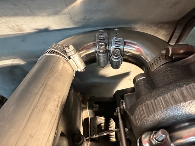
Now with the J-shaped header pipe attached on one side, and the 2" down pipe mounted on the other, we're almost there. This is the most nerve-wracking, brain-hacking, pucker-inducing part of the build.
To be sure, there is no "one" way to complete this final part of the fabrication of the exhaust pipe. I will present the method I used to connect the two ends of the pipe together, using the most straightforward routing I could think of to complete it.
This consists of the cutoff 45° fitting already clamped in place on the header side (see last post), a straight piece of pipe approximately 1-1/2" long, followed by a 90° elbow, and finally another 45° fitting that mates up to the vertical down pipe.
There is no way to clearly convey how to fit these four pieces together in every situation, other than to confirm that this method will work in this assembly, albeit with some tweaks and twists.
I would say the best way to approach this is by starting with the 90° elbow and short length of pipe approximately 1-1/2" long, but is NOT exact, and depending on your configuration could be longer or shorter. Either way, start with a longer piece and either tack weld it onto one end of the 90° elbow or use a clamp to hold the two parts in place. Then get a measurement or estimate how long the 90/straight piece needs to be.
Keep this in mind: Cutting ONCE will get you in trouble during this part of the fabrication. The only way to do this is to sneak up on it bit by bit. If you cut a piece too short, your done. You will need to get a new piece and start over.
Next, you will need to estimate how much to cut off the down pipe, which is too long, and fit a 45° fitting on top. Again, take your time and make multiple short cuts to zero in on the required length. The final connection to complete the assembly is between this 45° fitting and the 90° elbow installed previously. Use 2" clamps on all joints and only snug them enough to hold them together, but still allow rotational adjustments.
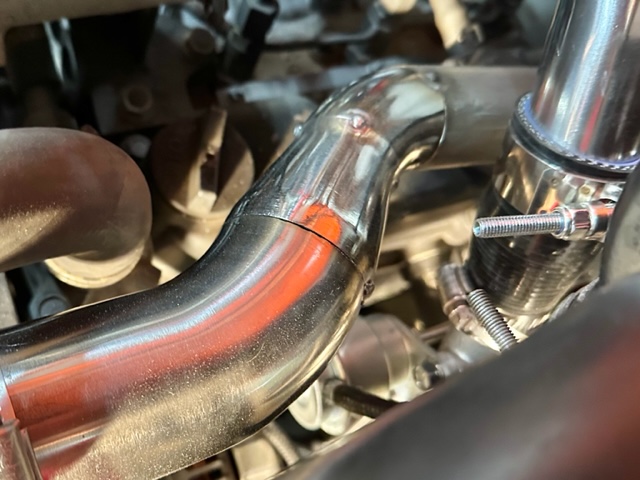
This is most likely the spot where you will loose your shit. Stop, take a breather, have a cold one, and get back to it. patience and persistence will pay off and you will finally have something that looks like this:
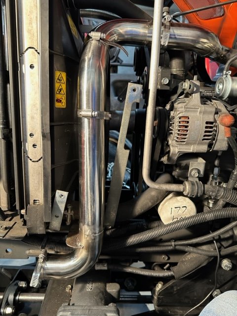
Here are a few more pictures from different angles for reference:

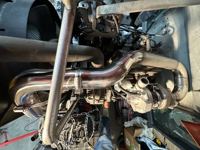
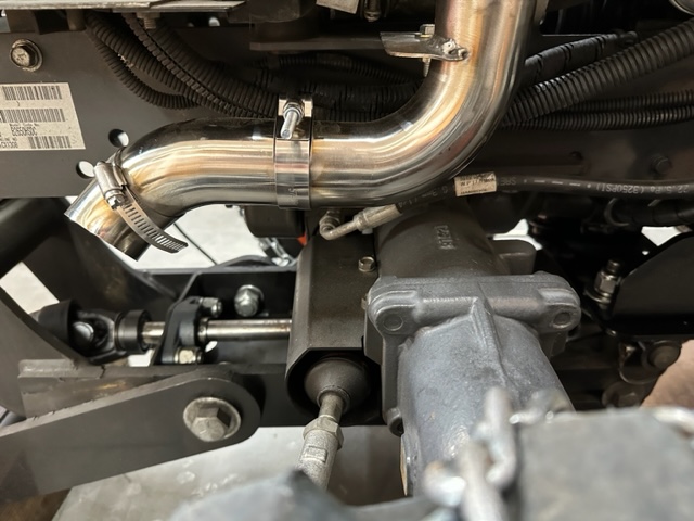
The final step is to add the tail pipe pieces in place. I used a long 45° fitting and a tight radius 45° fitting to direct the exhaust out in front of the axle and down in front of the tire. These were also clamped in place to hold them securely until tack welding. This is a personal choice and can be configured in almost any way to accommodate needs:

Once the tractor gods have smiled upon you and all the pieces line up, tighten all clamps as tight as possible without breaking them.
Now, very gingerly remove the screws holding the exhaust flange to the turbocharger and the bolt holding the down pipe in place on the lower frame. VERY CAREFULLY lift and move the clamped exhaust pipe assembly out of the engine compartment. This is kind of like playing a game of "don't bump the clamps" as you remove it. Generally, if the clamps are tightened snuggly, they won't be knocked out of position.
Now you can take the entire assembly to your welder and have everything tack welded as described in a previous post. Do not jump ahead and weld everything together with finished welds. The whole idea here is to test fit the assembly one more time after tack welding the clamped joints. If the exhaust pipe assembly fits as designed and everything is aligned properly, congratulations! If not, find the source of the ill-fitting section, grind off the tack welds and re-clamp it for another attempt. Believe me, it's a whole hell of a lot easier to deal with a tack weld than a finished weld.
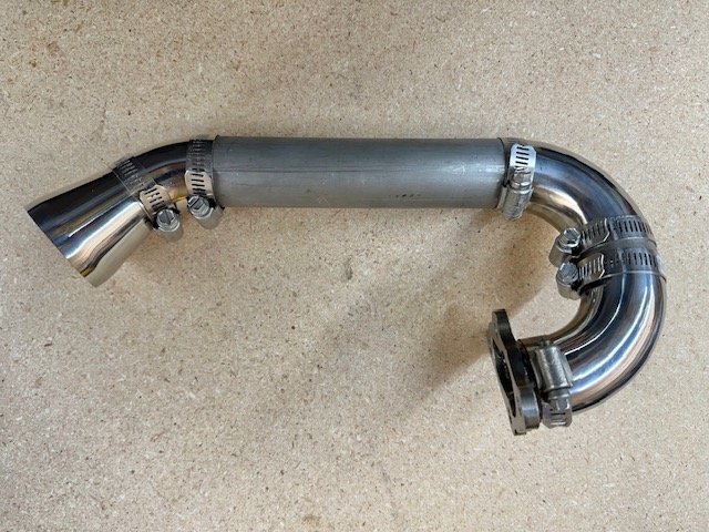
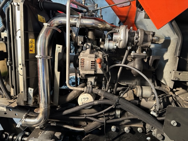
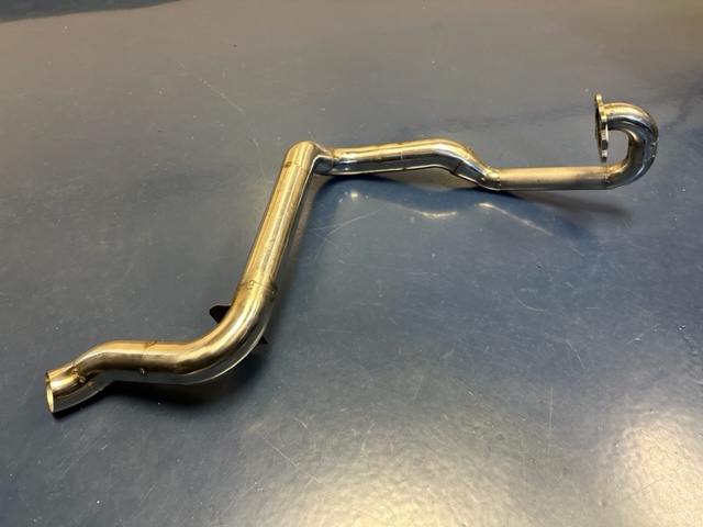
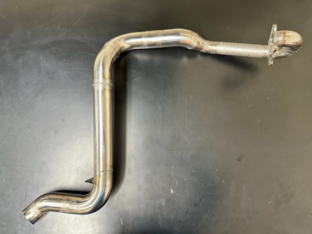
Once everything is aligned and fitting well, remove the exhaust pipe assembly and fully weld all joints. This will form a super strong and resilient exhaust pipe assembly. Here are some pics of my finished exhaust pipe for reference:
Well, there it is. . . A turbocharger modification from start to finish. This has been a helluva long process that started back in early summer and culminated in late October. I know we are well into November, but it took me that long to get caught up and post all relevant steps.
Much time and energy went into just researching and educating myself about tractors, turbochargers, atmospheric pressure, diesel engines, steel types, and fabrication techniques.
I must add a HUGE "Thank You" to Mike "Rdrcr" on this forum for leading the way and providing information and guidance. His help and patience made this project go much easier than it would have been without it. His generous attitude and approach was inspirational.
In the end, it turned out great, and the tractor has been run and tested, with the turbocharger humming along nicely. Exhaust Gas Temperatures were checked and found to be very reasonable, although until I get this beast out in the snow and start making rooster tails I won't know for sure. At that time I will add more test results and observations as I put time on it. For now, I am just RELIEVED to have this done!
As usual, stay tuned. . .
Solo
To be sure, there is no "one" way to complete this final part of the fabrication of the exhaust pipe. I will present the method I used to connect the two ends of the pipe together, using the most straightforward routing I could think of to complete it.
This consists of the cutoff 45° fitting already clamped in place on the header side (see last post), a straight piece of pipe approximately 1-1/2" long, followed by a 90° elbow, and finally another 45° fitting that mates up to the vertical down pipe.
There is no way to clearly convey how to fit these four pieces together in every situation, other than to confirm that this method will work in this assembly, albeit with some tweaks and twists.
I would say the best way to approach this is by starting with the 90° elbow and short length of pipe approximately 1-1/2" long, but is NOT exact, and depending on your configuration could be longer or shorter. Either way, start with a longer piece and either tack weld it onto one end of the 90° elbow or use a clamp to hold the two parts in place. Then get a measurement or estimate how long the 90/straight piece needs to be.
Keep this in mind: Cutting ONCE will get you in trouble during this part of the fabrication. The only way to do this is to sneak up on it bit by bit. If you cut a piece too short, your done. You will need to get a new piece and start over.
Next, you will need to estimate how much to cut off the down pipe, which is too long, and fit a 45° fitting on top. Again, take your time and make multiple short cuts to zero in on the required length. The final connection to complete the assembly is between this 45° fitting and the 90° elbow installed previously. Use 2" clamps on all joints and only snug them enough to hold them together, but still allow rotational adjustments.
This is most likely the spot where you will loose your shit. Stop, take a breather, have a cold one, and get back to it. patience and persistence will pay off and you will finally have something that looks like this:
Here are a few more pictures from different angles for reference:
The final step is to add the tail pipe pieces in place. I used a long 45° fitting and a tight radius 45° fitting to direct the exhaust out in front of the axle and down in front of the tire. These were also clamped in place to hold them securely until tack welding. This is a personal choice and can be configured in almost any way to accommodate needs:
Once the tractor gods have smiled upon you and all the pieces line up, tighten all clamps as tight as possible without breaking them.
Now, very gingerly remove the screws holding the exhaust flange to the turbocharger and the bolt holding the down pipe in place on the lower frame. VERY CAREFULLY lift and move the clamped exhaust pipe assembly out of the engine compartment. This is kind of like playing a game of "don't bump the clamps" as you remove it. Generally, if the clamps are tightened snuggly, they won't be knocked out of position.
Now you can take the entire assembly to your welder and have everything tack welded as described in a previous post. Do not jump ahead and weld everything together with finished welds. The whole idea here is to test fit the assembly one more time after tack welding the clamped joints. If the exhaust pipe assembly fits as designed and everything is aligned properly, congratulations! If not, find the source of the ill-fitting section, grind off the tack welds and re-clamp it for another attempt. Believe me, it's a whole hell of a lot easier to deal with a tack weld than a finished weld.
Once everything is aligned and fitting well, remove the exhaust pipe assembly and fully weld all joints. This will form a super strong and resilient exhaust pipe assembly. Here are some pics of my finished exhaust pipe for reference:
Well, there it is. . . A turbocharger modification from start to finish. This has been a helluva long process that started back in early summer and culminated in late October. I know we are well into November, but it took me that long to get caught up and post all relevant steps.
Much time and energy went into just researching and educating myself about tractors, turbochargers, atmospheric pressure, diesel engines, steel types, and fabrication techniques.
I must add a HUGE "Thank You" to Mike "Rdrcr" on this forum for leading the way and providing information and guidance. His help and patience made this project go much easier than it would have been without it. His generous attitude and approach was inspirational.
In the end, it turned out great, and the tractor has been run and tested, with the turbocharger humming along nicely. Exhaust Gas Temperatures were checked and found to be very reasonable, although until I get this beast out in the snow and start making rooster tails I won't know for sure. At that time I will add more test results and observations as I put time on it. For now, I am just RELIEVED to have this done!
As usual, stay tuned. . .
Solo
Last edited:
^^^^
Congratulations!!!
It looks great!
Well done!
I look forward to your future posts detailing the performance improvements. Did you increase/add more fuel? Also, I’d be curious to learn of your EGT readings. This data will be useful for any other forum members looking to add a turbocharger to their tractor.
Mike
Thanks Mike:
The tractor has been started up and run successfully with the turbocharger functioning well as far as I could tell. It was smooth and quiet through all RPM ranges without the PTO engaged, and EGT values looked good. There was one resonance I discovered on the exhaust pipe that I will detail later.
Other than running and basic functional verification, I have done nothing else to tweak or adjust anything. I will first see how it runs while throwing snow and make adjustments accordingly. Winter has set in up here, but it's mostly just cold with very little snow. That will change very soon I'm sure. That will start a whole new string of posts as I learn more about the operation and adjustments in a real world situation.
Solo
Surprise! Me again. . .
Several weeks ago was the official startup and testing of the new turbocharger modification. At that time, the engine, turbo, and new pipework all performed nicely at all RPM's without the PTO (snow blower) engaged. However, when I engaged the PTO and rev'd up the engine RPM's to full throttle, I observed a fairly significant mechanical resonance that had me concerned. The new exhaust pipe assembly was vibrating back and forth in the middle at very high speed, which appeared as a blur. Changing the RPM tamed it down, but I didn't want the possibility of damage or a broken weld in the future, so I knew I had to do something.
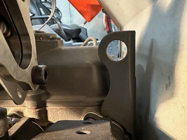
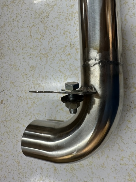
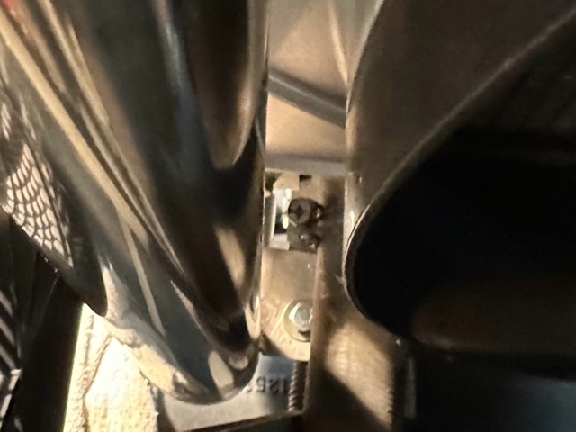
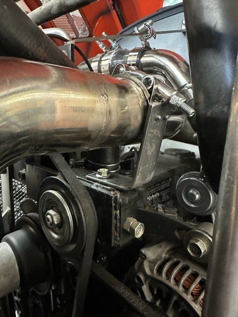
Originally, I was going to run a long brace (~12") from the middle of the exhaust pipe across the engine compartment to a solid hard point. Today, I went down in the dungeon to work on the beast and discovered a better, simpler option. The exhaust pipe passed right over the belt/pulley adjustment bracket, which was hard-mounted to the engine block and had a conveniently located hole:
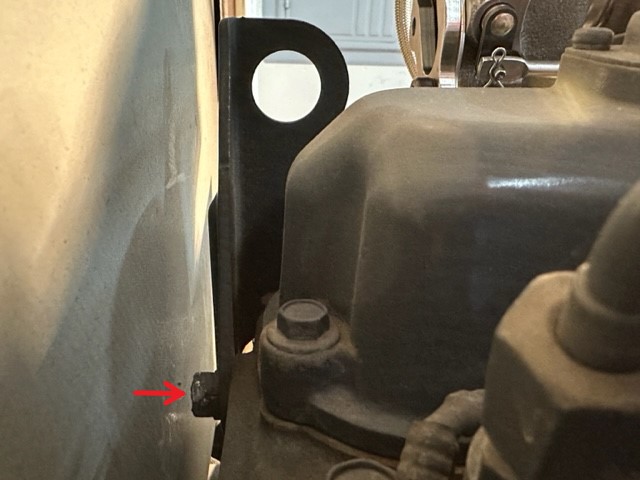
By utilizing a simple piece of steel bar, I was able to fabricate a bracket that would attach to the pulley bracket and a 2" clamp assembly. I attached the clamp end of the steel bar to the clamp with two pop rivets because of their thin heads, then drilled a hole on the other end to mount it to the pulley bracket:
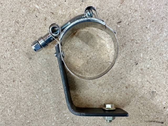
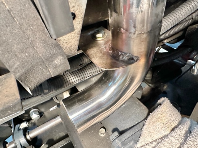
Because of a weld right at the location where the clamp attaches, I had to offset everything off a bit to one side, but it did not affect performance and mounted up quite nicely:
I fired the beast back up and took it out into the driveway to check the new modification. Result? No significant resonance at full RPM (2500) or any other RPM with the PTO engaged! Edit 1/1/24: After the initial test with heavy snow, I checked this dampener piece and found the vibrations had broken the clamp away from the bracket where the pop rivets held it together. I took the assembly off and pop-riveted it back together, then welded it on each side of the clamp to the bracket. I will be monitoring this in the future and will report back when I have more info.
These are the kind of things that can keep you up at night when running experimental equipment. Actually, I feel pretty lucky that it was a fairly simple problem that could be solved quickly and easily. It makes sense now: The new exhaust pipe assembly was attached originally on both ends, but not in the middle, leaving a resonant node that could vibrate at a certain mechanical speed (frequency). By making a simple bracket support the middle of the exhaust pipe, the resonance was damped out.
I am quite excited now to get the machine out in some real snow and start evaluating performance. My original goal was to recover the 24% loss of HP due to altitude, and maybe make a few extra pounds of pressure to boost performance. Guess it's a waiting game with the weather. Don't worry though, when I have some results, you guys will be the first to snow. . . errr. . . I mean, know!
Solo
Several weeks ago was the official startup and testing of the new turbocharger modification. At that time, the engine, turbo, and new pipework all performed nicely at all RPM's without the PTO (snow blower) engaged. However, when I engaged the PTO and rev'd up the engine RPM's to full throttle, I observed a fairly significant mechanical resonance that had me concerned. The new exhaust pipe assembly was vibrating back and forth in the middle at very high speed, which appeared as a blur. Changing the RPM tamed it down, but I didn't want the possibility of damage or a broken weld in the future, so I knew I had to do something.
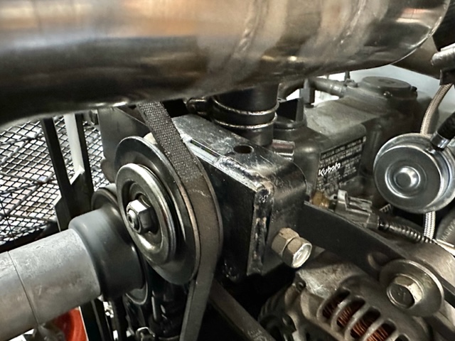
Originally, I was going to run a long brace (~12") from the middle of the exhaust pipe across the engine compartment to a solid hard point. Today, I went down in the dungeon to work on the beast and discovered a better, simpler option. The exhaust pipe passed right over the belt/pulley adjustment bracket, which was hard-mounted to the engine block and had a conveniently located hole:
By utilizing a simple piece of steel bar, I was able to fabricate a bracket that would attach to the pulley bracket and a 2" clamp assembly. I attached the clamp end of the steel bar to the clamp with two pop rivets because of their thin heads, then drilled a hole on the other end to mount it to the pulley bracket:
Because of a weld right at the location where the clamp attaches, I had to offset everything off a bit to one side, but it did not affect performance and mounted up quite nicely:
I fired the beast back up and took it out into the driveway to check the new modification. Result? No significant resonance at full RPM (2500) or any other RPM with the PTO engaged! Edit 1/1/24: After the initial test with heavy snow, I checked this dampener piece and found the vibrations had broken the clamp away from the bracket where the pop rivets held it together. I took the assembly off and pop-riveted it back together, then welded it on each side of the clamp to the bracket. I will be monitoring this in the future and will report back when I have more info.
These are the kind of things that can keep you up at night when running experimental equipment. Actually, I feel pretty lucky that it was a fairly simple problem that could be solved quickly and easily. It makes sense now: The new exhaust pipe assembly was attached originally on both ends, but not in the middle, leaving a resonant node that could vibrate at a certain mechanical speed (frequency). By making a simple bracket support the middle of the exhaust pipe, the resonance was damped out.
I am quite excited now to get the machine out in some real snow and start evaluating performance. My original goal was to recover the 24% loss of HP due to altitude, and maybe make a few extra pounds of pressure to boost performance. Guess it's a waiting game with the weather. Don't worry though, when I have some results, you guys will be the first to snow. . . errr. . . I mean, know!
Solo
Last edited:
Very nice. Congratulations on getting it completed, up and running. I appreciate you taking the time to share the trials, tribulations and successes of your project.Surprise! Me again. . .
Several weeks ago was the official startup and testing of the new turbocharger modification. At that time, the engine, turbo, and new pipework all performed nicely at all RPM's without the PTO (snow blower) engaged. However, when I engaged the PTO and rev'd up the engine RPM's to full throttle, I observed a fairly significant mechanical resonance that had me concerned. The new exhaust pipe assembly was vibrating back and forth in the middle at very high speed, which appeared as a blur. Changing the RPM tamed it down, but I didn't want the possibility of damage or a broken weld in the future, so I knew I had to do something.
Originally, I was going to run a long brace (~12") from the middle of the exhaust pipe across the engine compartment to a solid hard point. Today, I went down in the dungeon to work on the beast and discovered a better, simpler option. The exhaust pipe passed right over the belt/pulley adjustment bracket, which was hard-mounted to the engine block and had a conveniently located hole:
View attachment 115916
By utilizing a simple piece of steel bar, I was able to fabricate a bracket that would attach to the pulley bracket and a 2" clamp assembly. I attached the clamp end of the steel bar to the clamp with two pop rivets because of their thin heads, then drilled a hole on the other end to mount it to the pulley bracket:
View attachment 115923
Because of a weld right at the location where the clamp attaches, I had to offset everything off a bit to one side, but it did not affect performance and mounted up quite nicely:
View attachment 115917
I fired the beast back up and took it out into the driveway to check the new modification. Result? No significant resonance at full RPM (2500) or any other RPM with the PTO engaged!
These are the kind of things that can keep you up at night when running experimental equipment. Actually, I feel pretty lucky that it was a fairly simple problem that could be solved quickly and easily. It makes sense now: The new exhaust pipe assembly was attached originally on both ends, but not in the middle, leaving a resonant node that could vibrate at a certain mechanical speed (frequency). By making a simple bracket support the middle of the exhaust pipe, the resonance was damped out.
I am quite excited now to get the machine out in some real snow and start evaluating performance. My original goal was to recover the 24% loss of HP due to altitude, and maybe make a few extra pounds of pressure to boost performance. Guess it's a waiting game with the weather. Don't worry though, when I have some results, you guys will be the first to snow. . . errr. . . I mean, know!
Solo
The exhaust pipe is a thing of beauty. It looks like it could have come off a motorcycle. I do have two questions on the exhaust pipe, if you wouldn’t mind entertaining them.
1) Using the 1.5” and 2.0” diameter pipe appears to have been driven based on available geometric space and routing location. Is there any consideration for the pipe size based on flow requirements for the turbo’s/exhaust needs? Is there a reason you didn’t stay with 1.5” diameter throughout?
2) Do you think that if someone were to do this, that a different exhaust routing (such as straight up, through the hood, or to the side, though a hood panel) would be feasible? E.g. was there a technician or design need to exhaust near the stock location?
Thank you.
Hi GrizBota:
Glad you've been enjoying the build thread, it's taken years off my life. LOL. Those are two very good questions. I hope I can do them justice. . .
1) Using the 1.5” and 2.0” diameter pipe appears to have been driven based on available geometric space and routing location. Is there any consideration for the pipe size based on flow requirements for the turbo’s/exhaust needs? Is there a reason you didn’t stay with 1.5” diameter throughout?
You are correct; the pipe diameters were chosen based on sizing and room availability. I originally tried 2.5" diameter pipe, which proved to be beyond laughable. I decided to route most of the exhaust pipe in 2" diameter pipe, which worked for 75% of the pipe, but to be able to make the sharp turn and attach to the turbocharger required 1-1/2" diameter. So using a hybrid approach let me achieve the benefits of both without sacrificing performance. I have no solid numbers or test methods to prove this, other than what I could find on the internet forums and google searches. It does appear that larger compressor side piping is more critical for flow rates than the exhaust side piping, however.
2) Do you think that if someone were to do this, that a different exhaust routing (such as straight up, through the hood, or to the side, though a hood panel) would be feasible? E.g. was there a technician or design need to exhaust near the stock location?
I absolutely think you could literally route the exhaust pipe out of the engine compartment anywhere, in any direction. In fact, I actually was looking at the possibility of coming out of the turbo and going straight through the top of the hood with a short pipe. After further consideration, I figured it would be less dirty and not look like a hack to run it down and out like I did. This is truly personal preference, and you have every right to run it where you want. In the big picture, I don't think it will affect performance in the least. Do what works for you.
Thanks for the questions.
Solo
Success!
Things have been pretty quiet on this thread lately because I've been waiting for the weather to provide good conditions for the initial turbocharger test. Well, this morning after 2 days of snow I got my chance.
I was understandably nervous as I opened the garage door and stared out into a sea of white. I fired up engine and set the throttle for a warm up cycle. After a few minutes, I crawled up into the cab, reduced throttle to idle, and engaged the snow blower. With some trepidation I slowly started pulling throttle until I reached rated RPM (2500). I took a deep breath, released the brakes and started advancing into a foot of fresh-fallen snow.
I got a few feet in and realized that the tractor wasn't having any problem with a chute full of snow, effortlessly throwing a huge rooster tail. I pushed on with a steady foot on the pedal and froze my glance on the EGT gauge. 500, 600, 650, 700. At this point it slowed down until I started hitting a little deeper snow and taking a full-width bite. 750, 800, where it started leveling off. At one point I hit about 850 and looked down at the exhaust pipe through the window: There was a slight reduction in RPM as the engine was loaded, but instead of dragging the RPM way down and rolling coal, little if any black smoke came out of the exhaust pipe! YES!
Let me tell you what; 12" of new, wet, Rocky Mountain snow Could. Not. Stop. This. Beast!
I pushed on, making passes up and down the driveway, launching snow 40 to 50 feet off to the side. There was one test left that would reveal whether I was successful with this modification or not: Actuating the hydraulic chute rotator while fully loaded and moving steadily forward. I grabbed the handle and gave it a yank to the left. I watched the output of the exhaust pipe intently. OMG, NO SMOKE! At this point I was so excited I about pee'd myself! (well, that, and I'm old). This was completely a different machine from last year.
From then on, I was like a kid with a new Christmas toy, gleefully buzzing up and down the driveway throwing rooster tails like there was no tomorrow. All along, the engine and it's new turbo just hummed along, happy to be breathing normally again.
There has been much discussion on Rdrcr's post about fuel and timing adjustments to maximize performance and reduce black smoke. I could dive into that complicated subject and see what results I could achieve, although at this point I just don't think it's necessary, based on what I saw today.
As stated in the first post of this build thread, my goal was simply to recover the horsepower lost to the high altitude of my operating location. I have no dyno or way to provide hard numbers on the improvement, but from an operators subjective observations, the addition of a turbocharger to this particular tractor has been a resounding success. I do realize that I am on an adrenalin high right now, and could regret some of my statements later, but as it stands right now, I don't think that is going to happen. I will have the rest of the winter and many more storms to settle in with the tractor and get a relaxed assessment of the situation. As usual, I will post updates about the progress (or problems) encountered over the next few months.
Also, stay tuned and I'll make it worth your while. Here's a little teaser. . .
'Til then, Happy Snowblowing!
Solo
Last edited:
^^^^
It is certainly worth mentioning after your recent findings, some of the L2501 Turbo guys are running the Turbo Kits as altitude compensation only, like yourself and their fuel systems are untouched and unmodified. So there is no fuel adjustment (no additional or increase in fuel).
These guys are reporting a restoration of lost power (and a moderate increase in power), a reduction of smoke output and a 200-400 degree reduction of EGT temperatures.
There are many advantages to running the Turbo’s at elevation without having to adjust the factory fuel settings.
Mike
Hi Mike:
Indeed, this simplifies the whole operation by not requiring any fussing with fuel adjustments. Kind of a "one and done" installation.
When you think about it though, in a roundabout way the addition of a turbo for high altitude operation actually does change the fuel mixture of the machine by restoring lost air pressure. These machines are obviously designed and tuned for sea level operation. In essence, the machine has altitude sickness.
It's so worth it, I highly recommend this mod for anyone running high altitude operation. Thanks again for all your help.
Solo
Just a quick update. . .
Haven't had the kind of winter we had last year, when I was running the tractor every week or more. However, we have had several large storms dump some serious snow on us, and the tractor is handling it really well. I have made no fuel or timing adjustments, just the addition of the turbo, and the RPM's stay up better, the black smoke is greatly reduced, and the EGT's are behaving much better.
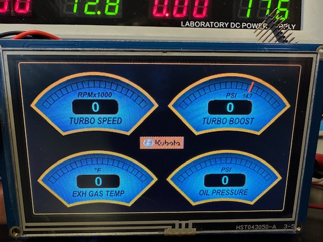
I haven't finished my instrumentation module yet, so I'm still in the dark about how much boost I'm actually generating, but hoping to have that working within the next few weeks. I'll keep everybody posted when that's up and running. Happy Winter!
Solo
Haven't had the kind of winter we had last year, when I was running the tractor every week or more. However, we have had several large storms dump some serious snow on us, and the tractor is handling it really well. I have made no fuel or timing adjustments, just the addition of the turbo, and the RPM's stay up better, the black smoke is greatly reduced, and the EGT's are behaving much better.
I haven't finished my instrumentation module yet, so I'm still in the dark about how much boost I'm actually generating, but hoping to have that working within the next few weeks. I'll keep everybody posted when that's up and running. Happy Winter!
Solo