Modifying 3 PtH on RS 1300 Tiller

Michbeck

Member

Equipment
B1181, G23 HD
Sep 29, 2011
80
0
6
Austria, Upperaustria
RS 1300 Tiller 3 Point Hitch Conversion

Hello to everybody!

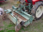
I recently bought a Kubota B1600DT with a RS 1300 Tiller. As I found out already, the tiller should be a Yanmar. Am I right with this assumption?

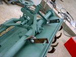
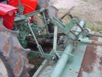
I am planning to mount a 3 point hitch on my Kubota and so I am thinking about modifying the tiller for 3 PTH mounting. Has anyone experience in such a project or can provide pictures of the same tiller with a 3 PTH?

I added 2 pics showing the tiller and the actual way it is mounted.

http://www.bilder-space.de/bilder/13c04d-1317735560.jpg
http://www.bilder-space.de/bilder/cd6b5a-1317735957.jpg

Regards,

Michi
 
Last edited:

284 International

New member

Equipment
B6000 with FEL, assorted Yanmar machines
Mar 25, 2011
151
0
0
California, USA
The RS1300 tiller is originally for a Yanmar, and should be a decent match for your tractor. The RS1400 tiller (The 1300/1400 designation is the width in millimeters) is the next size up and came on the back of 20 PTO hp Yanmar tractors, and the RS1300 was usually on the back of 16 PTO hp tractors.

I haven't converted a Yanmar tiller to three point, but I've done it to a Shibaura. It looks like the RS1300 is a two point style. The Yanmar tillers I've seen that attach in that fashion use a bracket bolted onto the tractor with two V-shaped tabs. The tiller mates to those, and the lifting links connect as shown in your pictures.

If yours has the same top tabs on the tiller, you might be able to use bushings and adapt the lift arm balls to the pins on the tiller, and just run a longer top link back to above where the hydraulic cylinder is mounted in the photograph. That hydraulic cylinder is different than original; they came with a threaded rod and hand crank wheel, but the result is the same.

On mine, I welded together an A-frame for the top link and used the original pins for the lift arms. I don't have pictures, but it's a pretty straight-forward fabrication job.
 

284 International

New member

Equipment
B6000 with FEL, assorted Yanmar machines
Mar 25, 2011
151
0
0
California, USA
Here are a couple photographs I found. The left one is a conversion a gentleman on another forum did to fit a Yanmar tiller behind his Massey Ferguson tractor. Without the extensions, he said his tires rub on the tiller when lifted.

The second picture shows the original Yanmar style 2 piece top link. It is designed to pin into two holes on the tractor, locking it rigidly into place. Then, it has a shorter link that connects the now fixed piece on the tractor to the tiller. Basically, it keeps the tiller from tilting when lifted, and letting the implement sit much closer to the tractor than would otherwise be necessary. You should be able to do something similar on your tractor: I'm sure Kubota setups are similar or identical in design, so it will be manageable.

You can also see the original threaded rod adjustment for the depth adjustment, as opposed to the hydraulic link in your photographs.

The third picture just gives an overall view of the original style setup for a three point hitch (and is of the same unit as in the second photograph.)

I hope this helps.
 

Attachments

Michbeck

Member

Equipment
B1181, G23 HD
Sep 29, 2011
80
0
6
Austria, Upperaustria
Thanks a lot for your detailed answer. I think it should be possible to convert the tiller.

First of all I'll do a paintjob on the tractor and mount the 3 PTH. Next spring I'll try to adapt the tiller. Of course I'll post pictures if I am succesful.
 

Michbeck

Member

Equipment
B1181, G23 HD
Sep 29, 2011
80
0
6
Austria, Upperaustria
I've got some new pictures from the tiller standing alone. I made a very simple shematic painting of how I think it should be possible to convert the tiller.

I am thinking of extending the lower linkage points and adding a bracing as shown on the first pic.
With a little bit of imagination you can see the a-frame and the bracing that connects with the coupling point above the hydraulic cylinder.

What do you think about it? Is this a possible way for a conversion?


284 International

New member

Equipment
B6000 with FEL, assorted Yanmar machines
Mar 25, 2011
151
0
0
California, USA
The tiller appears to be in good shape. I think it will work well for you.

As far as the conversion goes, you might want to keep your lifting points out closer to the end of the input shaft, unless it is removable. Because it is so long, I would be afraid that it would bind the PTO shaft when the tiller lifts and changes angle.

If you need to keep it closer to the tractor, I would try to set up the spacing of the mounting points so the tiller lifts level, rather than tilting up at the rear, to save the U-joints and input shaft.

One note for you: The bearing for the tiller shaft on the chain drive side is lubricated by the oil for the chain. The opposite bearing must be lubricated, it won't get oiled any other way.

This looks like a great project. Good luck, and keep pictures coming!
 

Michbeck

Member

Equipment
B1181, G23 HD
Sep 29, 2011
80
0
6
Austria, Upperaustria
You're right, the PTO shaft could become a problem. Before I continue I'll have a look if it is removeable and can be changed against a shorter one. If not, I'll have to think about something else.

Thanks for the moment, I'll keep you up to date!
 

284 International

New member

Equipment
B6000 with FEL, assorted Yanmar machines
Mar 25, 2011
151
0
0
California, USA
Even if you can't replace it, I think you should be safe with brackets making the tiller rise level, rather than tilting, as 3-point attachments normally do.
 

Michbeck

Member

Equipment
B1181, G23 HD
Sep 29, 2011
80
0
6
Austria, Upperaustria
As I said, I am trying to change the extra long pto-shaft to a normal one and so I disassembled the tiller and now I have no idea how it continues at this point. I've got the gearbox with the pto-shaft on the front and the driveshaft on the right side. The pto-shaft is held by two bearings. Here are some pictures:


Anybody an idea how to proceed here? Somehow I have to remove the bearings, I think, but how?
 

Michbeck

Member

Equipment
B1181, G23 HD
Sep 29, 2011
80
0
6
Austria, Upperaustria
I managed to disassemble the gearbox. Now I've got the long pto-shaft here.


Does anybody know if there is a short shaft available for such a tiller?

Would it be possible to shorten the actual shaft? If yes, how should it be done?
 

284 International

New member

Equipment
B6000 with FEL, assorted Yanmar machines
Mar 25, 2011
151
0
0
California, USA
I don't know of any shafts specifically to fit the tiller that are shorter. I'm certain it's possible to shorten the shaft, but I'm not sure that it could be shortened enough and still be strong enough to take the forces it would see if angled up and under power.

If I had to shorten it, I would use a piece of seamless steel tubing to sleeve the shaft once it was shortened. I'd probably do a couple plug welds on each end as well as welding the edges.

You are the person who can actually see what needs to be done, but if it were mine, I think I would change my bracket design, rather than cut and shorten a shaft and hope it survives. If that breaks, your tiller is probably useless.
 

Michbeck

Member

Equipment
B1181, G23 HD
Sep 29, 2011
80
0
6
Austria, Upperaustria
I was looking around and found this:


With this adapter I can shorten the shaft round 10 cm. I only have to dress the shaft to size. The shaft has 32 mm in diameter and the adapter 30 mm. So it should be still strong enough.
 

cabu

New member
Lifetime Member

Equipment
Kuno B1-15 (B1502DT)
May 24, 2009
736
2
0
Germany, Oyten
The tricky thing about that job will be to weld it straight on in line.
Good Luck

carl
 

284 International

New member

Equipment
B6000 with FEL, assorted Yanmar machines
Mar 25, 2011
151
0
0
California, USA
Michbeck, I'm not able to see your photographs. The links just take me to the page, and nothing happens except an occasional pop-up advertisement. I'm using a Mac with Firefox, so perhaps it's my system.

I'm guessing what you have is an adapter that can slide over the shaft, and has a 6 spline PTO male end. If they only will butt together, I wouldn't trust the new shaft to be strong enough or straight enough. If it slips over the shaft more than the shaft's diameter, you should be fine. It can be trued in a lathe or something, then tack welded, trued again, then welded completely. That should be strong enough, I would expect.

Is there a machinist you can ask for advice in your area?
 

Michbeck

Member

Equipment
B1181, G23 HD
Sep 29, 2011
80
0
6
Austria, Upperaustria
Yes, the pic shows such an adapter and it should at least slip over the shaft the size of the diameter.

I will ask someone who has an idea how to do this. Thanks for the moment. New pics as soon as possible.
 

Kubota Newbie

Active member

Equipment
M4500, New Idea Cut-Ditioner, JD 14T Baler, IH "Plow Chief" plows, Oliver Rake
Dec 28, 2010
531
81
28
Mount Vernon, Ohio
That's still probably going to be too long! Measure the smooth portion of the shaft just ahead of the bearing seal surface, check around to see if you can obtain a smooth bore/keyed clamp type PTO yoke to fit that diameter. If so, then you can have any machine shop cut the shaft and mill in a keyway (probably 1/4 or 5/16 inch square depending on the yoke). Your goal should be to have the back edge of the yoke around 1/2 to 3/4 of an inch in front of the gear box seal. The longer you can make the shaft between the set of PTO yokes on the tractor and the machine the better (within reason of course). You'll need it to be long enough to telescope the necessary amount to cover the range of motion from the top of the three point travel to the bottom (which is probably more than you'd think).
 

Michbeck

Member

Equipment
B1181, G23 HD
Sep 29, 2011
80
0
6
Austria, Upperaustria
I am not sure if I got this 100 %. You mean that the end of the pto-shaft should be 1/2 to 3/4 of an inch from the gearbox seal? 1 inch are 2.54 cm, this seems to be very very short for a pto shaft?

Or did I got something wrong?

Edit: You are talking about the back edge of the pto adapter, right?

With the adapter shown above I could achieve an overall length of the pto shaft of about 12 cm/4,7 inches
 
Last edited:

Michbeck

Member

Equipment
B1181, G23 HD
Sep 29, 2011
80
0
6
Austria, Upperaustria
Found another adapter:


It is availabe in 100 mm/3.94 inches and 75 mm/2.95 inches. The inner bore has an diameter of 22 mm.

Maybe the best solution. Dress the pto shaft to size, heat the adapter and press it onto the shaft. Additionally weld the front and maybe the back edge.

How short should the shaft be? Is the 3.9 inch short enough or is it better to go even shorter?
 

cabu

New member
Lifetime Member

Equipment
Kuno B1-15 (B1502DT)
May 24, 2009
736
2
0
Germany, Oyten
I am not sure if I got this 100 %. You mean that the end of the pto-shaft should be 1/2 to 3/4 of an inch from the gearbox seal? 1 inch are 2.54 cm, this seems to be very very short for a pto shaft?

Or did I got something wrong?

Edit: You are talking about the back edge of the pto adapter, right?

With the adapter shown above I could achieve an overall length of the pto shaft of about 12 cm/4,7 inches
Ich lese das so: 1/2 - 3/4" Distanz Getriebe zur Gelenkwelle.

Please make some pictures about the welding job.

der carl
 

284 International

New member

Equipment
B6000 with FEL, assorted Yanmar machines
Mar 25, 2011
151
0
0
California, USA
I think any of those adapters you have shown would be fine, as long as you can attach them over the original shaft and keep them aligned. I would suggest a slip clutch or shear bolt somehow, though.

I'm also still of the view that it would be easier to mount the top link further out over the lower link mounting points, and just use the factory ones. I don't think there's anything wrong with your plan, it simply seems to be more work. Is there a reason you're wanting to mount it that way?