L2272 3rd/QAR kit install How To

ACDII

Well-known member

Equipment
B2410, L352 Loader, Woods BH70-X backhoe
Oct 21, 2021
660
407
63
Illinois
The kit finally arrived last week and Friday I got started installing it. Had to stop at a point since I needed a wrench I didn't have. This is a complete walk through of all the components.

I will be posting the varius steps in separate posts due to the amount of photos I took.

IMG_8378.JPG
IMG_8379.JPG
IMG_8380.JPG
IMG_8381.JPG
IMG_8382.JPG
 
Last edited:

ACDII

Well-known member

Equipment
B2410, L352 Loader, Woods BH70-X backhoe
Oct 21, 2021
660
407
63
Illinois
The first step is to remove 2 bolts from the frame where the loader frame bolts to and install the bracket that supports the 3 lines from under the seat to the valve assembly.

IMG_8383.JPG


I found that they were all loose and I had to realign and tighten up the top bolt.
IMG_8384.JPG

Reuse the washers and nut, toss the bolts.

this is the bracket and included bolts.
IMG_8385.JPG


Tighten to 166 ftlbs.
IMG_8386.JPG


Next, mount the valve assembly. You will want to get a 10mm x 1.25 tap and run it through the holes as they will be filled with paint. There are spacers between the assembly and frame.
IMG_8387.JPG
IMG_8388.JPG


Go over all the fittings, I found the top one was leaking. Also keep all the caps on everything, only remove them when attaching the lines.
 

ACDII

Well-known member

Equipment
B2410, L352 Loader, Woods BH70-X backhoe
Oct 21, 2021
660
407
63
Illinois
Next up, there are 2 solid lines and one hose. These attach between the valve assembly and the frame bracket from step 1. Tighten the bulkhead nuts with a 15/16 wrench, if you have two even better, or use a crescent, but do this before attaching the lines, or you might have trouble getting access.

The lines
IMG_8389.JPG


First line, its the 90* bent one
IMG_8390.JPG


I then attached the 3rd line, the one with all the bends. The rubber one goes in between them and I found it easier to install the long one first.
Here you can see where the short one attaches to the assembly.
IMG_8391.JPG


Here is where the long one attaches.
IMG_8392.JPG


The next step is to attach the connector brackets. Third function is the rear most, the Quick Attach remote is sandwiched between it and the frame.

Here is where I ran into an issue. According to the manual, the bracket for the loader connectors is supposed to be attached on the outside of the frame, it was attached on the inside, and me being me, forgot the second bracket for the QAR so the bolts were too long.
IMG_8393.JPG


So I moved the loader bracket to the outside and no issues with clearance. Then discovered, oops, missed the second bracket. Mounted that and the bolts would have cleared.
IMG_8396.JPG
IMG_8398.JPG


So I left it.

Attached the lines between the valve assembly and connectors.

Top ones are the 3rd function, bottom for the QAR
IMG_8399.JPG
IMG_8400.JPG


I started work on the cab components, found I didn't have a 1 1/16" combo wrench for the fittings, and decided to skip ahead to the loader components. Thats when I discovered another issue that I have yet to determine the cause. By moving the bracket to the outside, the bucket tilt stopped working!

Moving it out 1/2" caused a hose to become pinched maybe? I moved the bracket back to it's original location and tilt started working. At this point I decided to call it a day, it was getting late and i was getting hungry.
 

ACDII

Well-known member

Equipment
B2410, L352 Loader, Woods BH70-X backhoe
Oct 21, 2021
660
407
63
Illinois
Day 2. Ran out and got a wrench that fits and got started on the cab. First thing I discovered, that seat is freaking HEAVY!!! Once I got it up and locked I found there is just not enough room to work, nor get the leverage needed to crack the lines, so I removed the seat.

two bolts at the front, 17mm wrench, seat comes out the back window. underneath are 4 more 12 mm wrench nuts, remove those the and suspension plat comes out. This is the heavy part of the seat. I removed it via the left door. Then at the back of the seat platform are two more bolts, 12mm wrench and they come out. then the whole plate comes out giving full easy access to the top of the HST.

The part to remove is that hex tube running between the two pipes just in front of the 3pt .
IMG_8402.JPG


Now I can get both wrenches, a 1" on the pipe and 1 1/16" on the nut, and crack them loose. I took a dead blow and gave the wrench a couple whack to break it loose at both ends.

Once that is out, there are two new fittings to install on each pipe. These are where two lines are connected.
IMG_8403.JPG


There is a plug forward and to the left that requires a allen type bit. You have to pound it down to get through the paint, but the plug comes out easily. Before removing ti, work the bit back and forth to remove it. Then install the third fitting and position it at 45* and lock it down.
IMG_8404.JPG


IMG_8405.JPG


Now if you look at the photos above before the hoses are installed, if you have the rear remotes, the block has a very sharp corner to it, so make sure you put the hoses above and away from that corner so they aren't rubbing on it.
IMG_8406.JPG


Sorry, didn't know it was blurry until I posted but you can see enough to get the idea.

Next, run the lines down on the right side at the front corner, then attach them to the bulkhead fittings from step one.
IMG_8407.JPG


Here is where teh hoses fit best after all was connected up. The Power Beyond hose, which is the one on the right is longer than the others and rather than having it sticking out underneath, moved it to the outside of the return hose.
IMG_8408.JPG


Last step is to secure the lines to the frame using existing bolts and two clamps included with the kit.
IMG_8409.JPG


These lines will make HST fluid changes FUN!!!! They are right under the filters so will need to be unclamped and tied out of the way.
 

ACDII

Well-known member

Equipment
B2410, L352 Loader, Woods BH70-X backhoe
Oct 21, 2021
660
407
63
Illinois
Next up are the electrical connections. I left the seat out still until I was completely done as it gave me a lot of working area to get these harnesses routed and secured. Pull the rubber handle off the 3pt lever, remove the top cover, disconnect the lighter socket harness and the PTO switch harness, and lift the cover off. Then remove the metal side cover as you need full access here. Leaving the set out and putting the cover in place makes this a lot easier to work on.

First thing is to remove the old handle with the throttle up switch and replace it with the included one with the thumb rocker. It requires some cutting of the sleeve and the boot for the second harness and 3rd function activation switch. Sleeve is cut down to 60mm.
IMG_8410.JPG


Then route the cables up and around the side. There is a plug you have to reattach for the throttle up just under the boot.
IMG_8411.JPG


At tha back of the cab there is a plug to remove, cut an X through it and feed the harnesses through it, then reinstall it in the hole.
IMG_8412.JPG


Run the harnesses to the front and make all the connections. This is a bit tricky as the plugs have to be sorted out between the two harnesses.

To avoid confusion, I have a control panel for my sprayer coming out, so that is what that plug is in the below picture.
IMG_8413.JPG


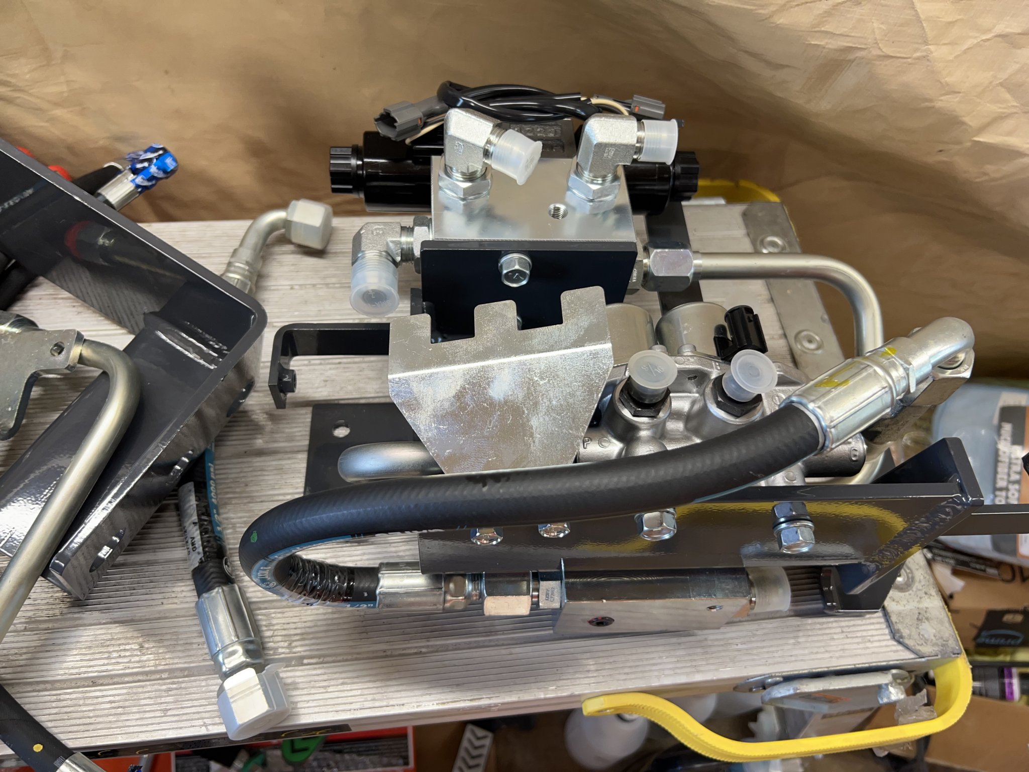
There are three relays to mount, placement doesn't matter as they are all the same, two connect to one harness, one to the other.
IMG_8416.JPG


There are 2 solenoids at the top, they connect to the harness with one relay connection, these are the 3rd function valves. There is a third valve buried in the back of the assembly that attaches to the other harness.

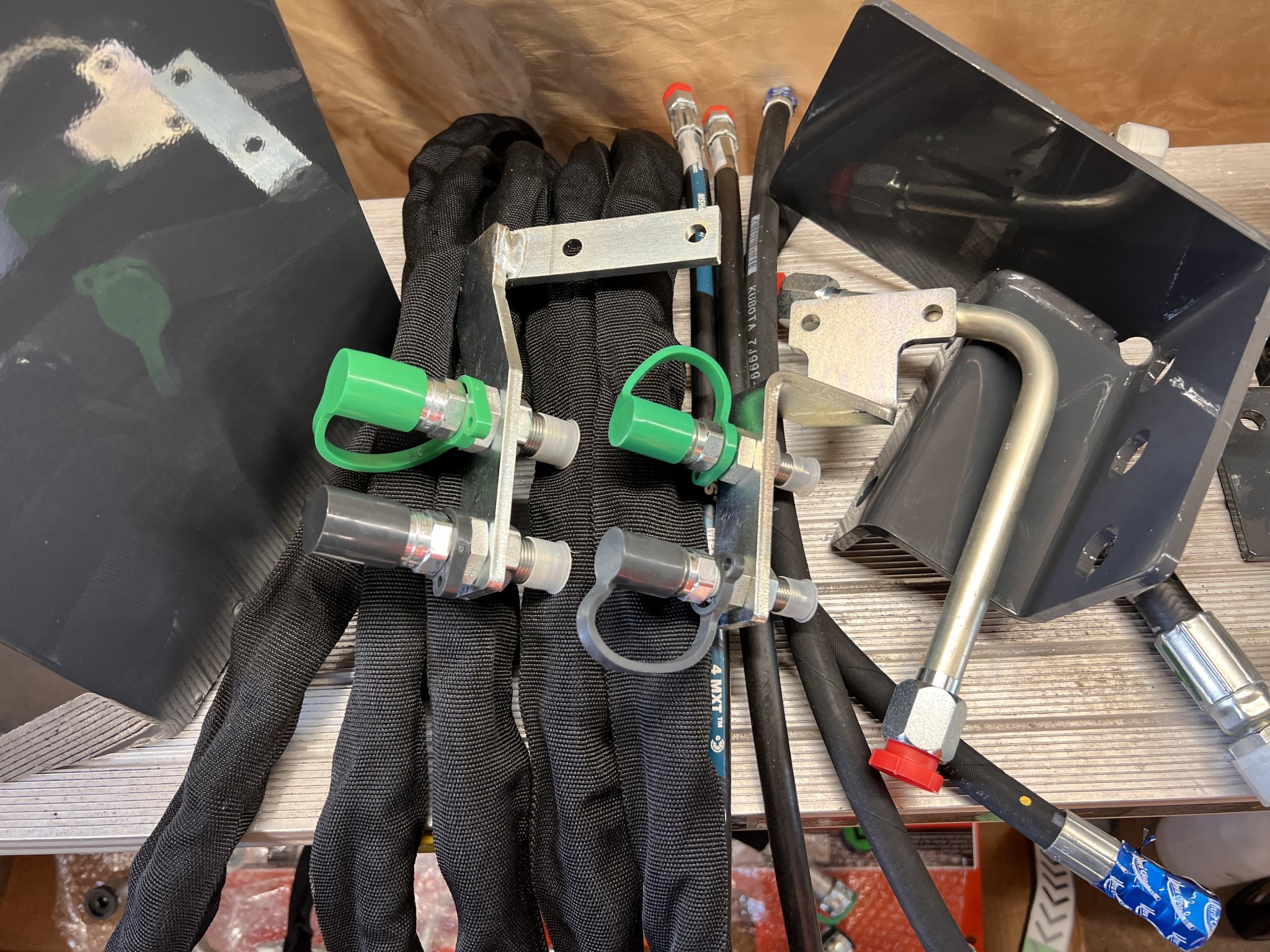
NOTE on the front valves, there is a connector on the harness with a black wire and a red striped wire, this connects to the front solenoid shown below.

IMG_8417.JPG


If you look close at the bottom of the above picture, there are two connections that are not apparent. The plugs are fixed to the solenoids and have rubber plugs in them. The other harness connects to these.


Then bundle both harnesses and attach them with the included tie wrap as shown.
IMG_8418.JPG


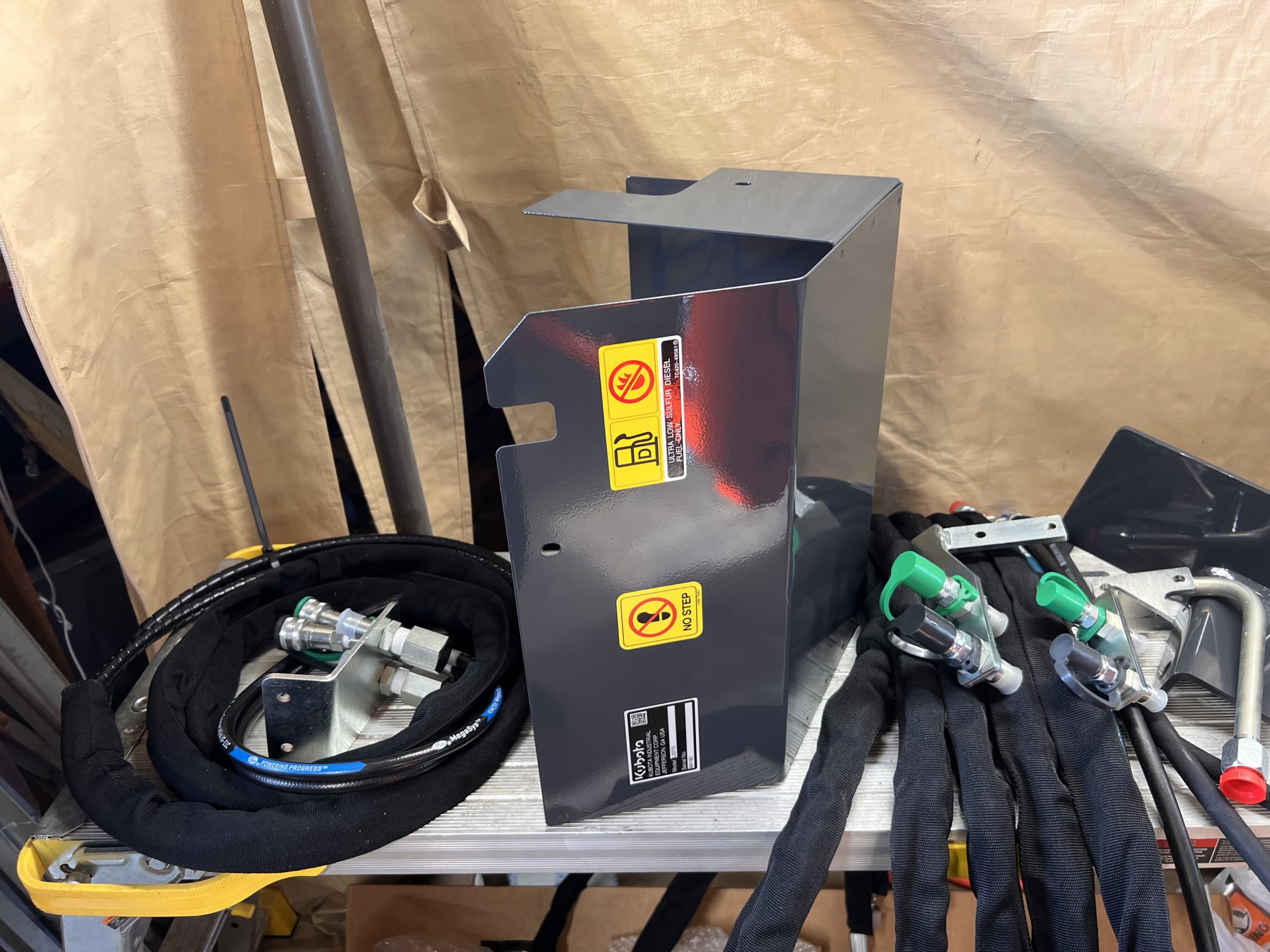
Once this is all done, install the shield. What I did is put some electrical tape on the edges where the hoses exit since they appear to want to rub there.
IMG_8414.JPG
IMG_8419.JPG


Back in the cab, there is a split power harness with green fittings, plug both harnesses into that, then connect that to the matching plug from behind the side panel. I didn't photo this because I have 3 more cables running through here that stock tractors wont have, they are for the subwoofer connections and power from the battery, the jumble would make it confusing. However, the harness connections are straight forward, the 3rd function connects to power and the harness from the handle and the other connects to the pair of switches to be installed in the cover. Once connected, put the covers back in place. If you removed the seat, reinstall it, otherwise the tractor side is done.
IMG_8437.JPG
 
Last edited:

ACDII

Well-known member

Equipment
B2410, L352 Loader, Woods BH70-X backhoe
Oct 21, 2021
660
407
63
Illinois
Final installation is on the loader itself. There are 3 separate hoses to run through the frame, so first step is to remove the covers on the right side of the loader (looking forward from drivers seat), then feed the spiral wound fittings through, and then each third function line.

Lift the loader up and tilt the attachment bracket level, makes it easy to work on, and set it at a comfortable height. Remove both levers and the pins. You will need to disassemble the pins and replace everything except the spring and lower pin. Reassemble and compress the spring to 71mm
IMG_8420.JPG


Note the differences, original is on the right.
IMG_8422.JPG


Reassemble using the included cotter pins.
IMG_8421.JPG


Next up, install the new levers, these will be tight fitting on the pin blocks, use the new bolts to secure them.
IMG_8423.JPG


Tighten the nut down to where the spring is 35mm high, then install a second nut and lock it in place.
IMG_8425.JPG


Test to make sure they work as they should. Take a razor blade and cut away the paint on the fitting where the cylinder attaches, apply some grease to the inside of the hole and on the bung, and install the cylinder. The fixed side in on the left, the piston side the right.


Connect the lines, plug in the hoses at the connectors and give it a test.
IMG_8426.JPG
IMG_8427.JPG
IMG_8428.JPG
IMG_8429.JPG


Next up, secure the brackets to the shield on the loader. I found it easier to remove the shield, mount the brackets and reinstall the shield.
IMG_8430.JPG
 

ACDII

Well-known member

Equipment
B2410, L352 Loader, Woods BH70-X backhoe
Oct 21, 2021
660
407
63
Illinois
Continued

IMG_8431.JPG
IMG_8432.JPG


Next, pull the QAR hoes out until you find the tape on each line. These are your marks for attaching to the hold down clip. This gives a pre-determined length to allow full movement.
IMG_8433.JPG

IMG_8434.JPG


Install the cover to the back of the QA frame. On mine I had to beat a few brackets into submission ans they were not aligned right. Run a 8mmx 1.25 tap through the 5 holes to clean them.
IMG_8435.JPG


If you notice in the above picture, when I attached the 3rd function lines, I found they are the long lines and the bracket had to be moved over to the center. You might want to check line length before mounting the bracket so you don't have to do it twice like I did.

Secure the hoses at the connector side after getting them all equal length.
IMG_8436.JPG


Run everything now and check for leaks. The 3rd function does not come with fittings, you can use which ever style fits your needs.

IMG_8438.JPG


All done.
 
Last edited:
  • Like
Reactions: 1 user