HenroThank you for posting those diagrams. If you look closely, they both show one of the two coils shorted across by a wire.
This confirms the error I was referring to. If each side of a coil is connected to the same point, electrically it can not operate.
So the diagrams are obviously in error, if the explanation of operation is correct.
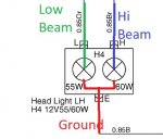
Please look closely at the attached headlight wiring. This is an exact parallel to the engine stop solenoid.
The headlight bulb has two filaments within one glass envelope. The filaments are actually coils of wire which glow when current flows through them.
One filament is rated for 60 watts which is the high beam. The other filament is rated for 55 watts which is the low beam.
Both filaments share the same ground path but each has its own power wire.
Think of the high beam filament as the pull in coil within the solenoid envelope. Think of the low beam filament as the hold coil within the solenoid envelope.
Wiring schematics and illustrations can be misleading and are not as clear as if you had a component on the work bench.
Dave
Attachments
-
 28 KB Views: 204
