Hazard Lights Troubleshooting

Jonny4523

Member

Equipment
L4310 HST
Nov 10, 2022
30
2
8
Lafayette, IN
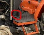
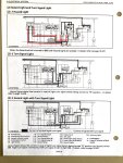
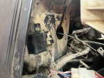
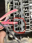
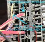
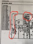
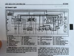
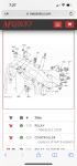
I’m trying to get the hazard lights working on my L4310. The shop manual shows the hazard unit, hazard relay, and turn signal relays all being separate. But the parts manual only shows a hazard unit (which physically matches the tractor). I’ve already replaced the hazard unit and the hazard switch on the dash. I’ve also supplied a separate 12V to the hazard lights to make sure they are good. One clue I have is that the light is illuminated on the hazard switch, whether it’s pushed in or not. Which makes me think something is wrong with the hazard relay. But I can not seem to find seperate relay for the hazards and turn signals. When I turn on the turn signals, I can hear the relays activating, but lights on the dash don’t light and the turn signal doesn’t work on the back.

Any ideas?
 

Attachments

Yooper

Well-known member
Lifetime Member

Equipment
3901 LA525
May 31, 2015
1,460
432
83
NE Wisconsin
Classic ground issue. Is a ground location schematic available?
 
  • Like
Reactions: 1 users

N3BP

Active member

Equipment
B7200DT, B7200HST-D, L2900GST, L3010 HST TLB
Sep 20, 2016
392
148
43
Lebanon, PA
A few things.....

-Two electrical systems exist for this particular machine based upon your serial number. It looks like the split was serial# 60079/60080. Is yous above or below this?

-Second thing is peal back the rubber cover at the bellhousing and have a peak at the wiring inside there. Mice love to build big bushy nests in there and gnaw on the wring. (see pic for location)

I have to double check but I believe the hazard illumination switch illuminates when you turn the headlight switch on, regardless if the hazard lights are on or off.
 

Attachments

Jonny4523

Member

Equipment
L4310 HST
Nov 10, 2022
30
2
8
Lafayette, IN
A few things.....

-Two electrical systems exist for this particular machine based upon your serial number. It looks like the split was serial# 60079/60080. Is yous above or below this?

-Second thing is peal back the rubber cover at the bellhousing and have a peak at the wiring inside there. Mice love to build big bushy nests in there and gnaw on the wring. (see pic for location)

I have to double check but I believe the hazard illumination switch illuminates when you turn the headlight switch on, regardless if the hazard lights are on or off.
my serial number is 60661. I have already cleaned that area out. I think I had a short earlier in the area due to caked up mud. I’ll check again.
 

N3BP

Active member

Equipment
B7200DT, B7200HST-D, L2900GST, L3010 HST TLB
Sep 20, 2016
392
148
43
Lebanon, PA
Pull the plugs apart in that area too and make sure none of the terminals turned green and corroded on you. Also, and I assume you did this, but check your fuses. I believe one of them is dedicated to to the hazard lights. If this doesn't resolve your issue than take a look at my attachment. I drew in red the area you need to take a close look at. If there is an open in any of these wires, your hazzards won't work, or dash indicator won't work, or both won't work simultaneously. The last component the current passes through isn't the hazard relay or switch, but turn signal relay. You should have two of them (and maybe both are combined into a single component). If current isn't leaving the output terminal of those relays, then they might be bad, although an open seems more likley. I would run a jumper from the output terminal of the turn signal relays to the hazzard lights and see if they illuminate. That terminal would be the one with the red wire w/ white tracer for right signal, green wire w/ white tracer for left signal.
 

Attachments

  • Like
Reactions: 1 user

Mark_BX25D

Well-known member

Equipment
Bx25D
Jul 19, 2020
1,611
1,140
113
Virginia
Pull the plugs apart in that area too and make sure none of the terminals turned green and corroded on you. Also, and I assume you did this, but check your fuses.

Yep. Take apart and clean every connection. Use a commercial contact cleaner for any connection that has a plastic housing. CRC is good stuff. Good for the innards of switches, too.

For the ground connections, take them apart and clean them down to shiny, bare metal. Add some dielectric grease to prevent corrosion, then reassemble.
 
  • Like
Reactions: 1 users

Jonny4523

Member

Equipment
L4310 HST
Nov 10, 2022
30
2
8
Lafayette, IN
Classic ground issue. Is a ground location schematic available?
I have been looking and I can't find a ground location schematic. The only locations I've found so far are at the fuse box, the battery, and the hazard lights themselves (which I checked with giving them 12V from the tail lights and using their own ground).
 

Jonny4523

Member

Equipment
L4310 HST
Nov 10, 2022
30
2
8
Lafayette, IN
A few things.....

-Two electrical systems exist for this particular machine based upon your serial number. It looks like the split was serial# 60079/60080. Is yous above or below this?

-Second thing is peal back the rubber cover at the bellhousing and have a peak at the wiring inside there. Mice love to build big bushy nests in there and gnaw on the wring. (see pic for location)

I have to double check but I believe the hazard illumination switch illuminates when you turn the headlight switch on, regardless if the hazard lights are on or off.
I pealed back that cover tonight and disconnected all connections. I blew all the junk out of them and sprayed them down with CRC mass flow sensor cleaner. But they all looked to be in really good shape. No signs of corrosion.

As far as the hazard illumination, it illuminatesd in both the hazard on and hazard off condition.
 

Jonny4523

Member

Equipment
L4310 HST
Nov 10, 2022
30
2
8
Lafayette, IN
Pull the plugs apart in that area too and make sure none of the terminals turned green and corroded on you. Also, and I assume you did this, but check your fuses. I believe one of them is dedicated to to the hazard lights. If this doesn't resolve your issue than take a look at my attachment. I drew in red the area you need to take a close look at. If there is an open in any of these wires, your hazzards won't work, or dash indicator won't work, or both won't work simultaneously. The last component the current passes through isn't the hazard relay or switch, but turn signal relay. You should have two of them (and maybe both are combined into a single component). If current isn't leaving the output terminal of those relays, then they might be bad, although an open seems more likley. I would run a jumper from the output terminal of the turn signal relays to the hazzard lights and see if they illuminate. That terminal would be the one with the red wire w/ white tracer for right signal, green wire w/ white tracer for left signal.
I pulled the plugs. No signs of corrosion. I blew them out and sprayed with some air mass flow cleaner to be safe. Fuse was good. That was my first check.

My WSM is showing the hazard relays, hazard units, and turn signal relays all being seperate. I even found a picture in the cabin portion that shows a row of relays. My tractor does not reflect that. I appears they were all combined (see attached picture).

I'll try your jumper suggestion at my next opportunity.
 

Attachments

Jonny4523

Member

Equipment
L4310 HST
Nov 10, 2022
30
2
8
Lafayette, IN
Yep. Take apart and clean every connection. Use a commercial contact cleaner for any connection that has a plastic housing. CRC is good stuff. Good for the innards of switches, too.

For the ground connections, take them apart and clean them down to shiny, bare metal. Add some dielectric grease to prevent corrosion, then reassemble.
I'm having trouble finding very many ground connections. The one that I've found is behind the fuse box. It looks to be in great condition. I've tested continuity from it to the hazard bulb bases and it was strong. I was hoping my WSM would show electrical ground locations, but I haven't had any luck so far.
 

Jonny4523

Member

Equipment
L4310 HST
Nov 10, 2022
30
2
8
Lafayette, IN
Pull the plugs apart in that area too and make sure none of the terminals turned green and corroded on you. Also, and I assume you did this, but check your fuses. I believe one of them is dedicated to to the hazard lights. If this doesn't resolve your issue than take a look at my attachment. I drew in red the area you need to take a close look at. If there is an open in any of these wires, your hazzards won't work, or dash indicator won't work, or both won't work simultaneously. The last component the current passes through isn't the hazard relay or switch, but turn signal relay. You should have two of them (and maybe both are combined into a single component). If current isn't leaving the output terminal of those relays, then they might be bad, although an open seems more likley. I would run a jumper from the output terminal of the turn signal relays to the hazzard lights and see if they illuminate. That terminal would be the one with the red wire w/ white tracer for right signal, green wire w/ white tracer for left signal.
Well, even if it is 2am, curiosity got the best of me and I went back out to the garage. I found 1 wire coming into the hazard unit (all red) that appeared to give me battery voltage to ground (ground here being the mounting screw that the hazard unit bolts to, which I believe serves as its body ground). So I jumpered between it and both the red wire / white tracer and green wire w/ white tracer. No illumination.

I then jumpered between each of these two wires and my work light connection on the back that I know is good. Boom, I get each light to illuminate. So I know my wires are good from that connector back to the hazard lights.

So I retry from what I believe is my hot wire coming in and still no light.

Dumbfounded by this, I decide to jumper straight to each of these wires from the hazard fuse. No light. But then I jumpered off the work light fuse and bam, we have light. So I verified voltage from a mounting bolt to each of the fuses. Sure enough, no juice getting to the hazard fuse.

So my next step will be to pull the fuse box and try to figure out why I have no juice getting to that fuse. All other fuses had battery voltage.
 

Jonny4523

Member

Equipment
L4310 HST
Nov 10, 2022
30
2
8
Lafayette, IN
Ok, 3am update because I just couldn't leave it alone. Took another look at my WSM and saw that I should have 12V to the hazard lights straight from the battery. Pulled the fuse block and I was able to measure battery voltage to the back of the fuse block. So I know my wiring is good from the battery to the fuse block.

I'm pretty sure it's a corrosion issue now. Tomorrow I'll pop off the positive cable of the battery and then see if I can pull out the blade shown in the attached picture to clean everything up.
 

Attachments

  • Like
Reactions: 1 user

Yooper

Well-known member
Lifetime Member

Equipment
3901 LA525
May 31, 2015
1,460
432
83
NE Wisconsin
I think you’re on to it now. The late night diligence paid off. Chasing electrical issues is probably my least favorite thing to do but we all have to face the fact that everything is electrical now.
 
  • Like
Reactions: 1 user

N3BP

Active member

Equipment
B7200DT, B7200HST-D, L2900GST, L3010 HST TLB
Sep 20, 2016
392
148
43
Lebanon, PA
Looking at your pic, the relay on the left is the L&R turns signal / hazard unit, the one on the right is the starter relay. So they did combine the three separate functions into on relay, and I think the serial number split is where this update occurred. Apparently they didn’t update the WSM after doing this, which does make troubleshooting more difficult as the wiring is different. My WSM also shows the old style like you have. You also won’t find any grounding details or locations, but I think that’s not your problem anyway.

No need to look at the battery connection if you have 12V to the fuse box. You’ve troubleshooted the problem down to the load side of the fuse socket to the hazard relay input. It’s the red 0.85 mm2 wire.

See attached pic. Place a jumper between the two and it should work. Note the WSM indicates there are two smaller red wires leaving that area of the fuse block. One is a 1.25mm2 size to feed the timer relay, and the other the 0.85mm2 size one to feed the hazard. I think one of those wires is hidden behind the larger one in your pic. You want the smaller of the two.

You very well could have a corroded female terminal in the fuse box. Sometimes they also loosen up a bit and don’t bite on the fuse well. You can get a small flathead screwdriver and try and tighten it up.
 

N3BP

Active member

Equipment
B7200DT, B7200HST-D, L2900GST, L3010 HST TLB
Sep 20, 2016
392
148
43
Lebanon, PA
Correction, I was looking at the diagram incorrectly, so disregard my above post.....
 

N3BP

Active member

Equipment
B7200DT, B7200HST-D, L2900GST, L3010 HST TLB
Sep 20, 2016
392
148
43
Lebanon, PA
These Kubota wiring diagrams will strain even the best eyes!


Please see attached. You should have 12V on the larger red wire w/ white tracer. This is the constant supply to the hazard assembly regardless of ignition key position. No voltage here indicates an open between this point and the battery.

If you have 12V present, then place a jumper between it and the smaller white wire w/ red tracer. This is the feed to the hazard switch. Hazzards should work. If they do not, then you have an open in this wire, or the hazard unit is bad.
 

Attachments

Jonny4523

Member

Equipment
L4310 HST
Nov 10, 2022
30
2
8
Lafayette, IN
These Kubota wiring diagrams will strain even the best eyes!


Please see attached. You should have 12V on the larger red wire w/ white tracer. This is the constant supply to the hazard assembly regardless of ignition key position. No voltage here indicates an open between this point and the battery.

If you have 12V present, then place a jumper between it and the smaller white wire w/ red tracer. This is the feed to the hazard switch. Hazzards should work. If they do not, then you have an open in this wire, or the hazard unit is bad.
Actually, in that picture, the hazard is the second from the bottom on the left side. The bottom right wire is the constant +12V from the battery that supplies both the hazard and the ignition cutoff. I was able to jumper 12V from another fuse last night and my flashers were in full function. When I pulled the fuse block off, I was able to measure +12V in the back of the block, but not the front. So I’m confident that’s where my problem lies.

So tonight’s task will be to pull the positive cable off the battery so I can try to take that supply blade out of the back of the fuse block and give it a good cleaning.
 

N3BP

Active member

Equipment
B7200DT, B7200HST-D, L2900GST, L3010 HST TLB
Sep 20, 2016
392
148
43
Lebanon, PA
Actually, in that picture, the hazard is the second from the bottom on the left side. The bottom right wire is the constant +12V from the battery that supplies both the hazard and the ignition cutoff. I was able to jumper 12V from another fuse last night and my flashers were in full function. When I pulled the fuse block off, I was able to measure +12V in the back of the block, but not the front. So I’m confident that’s where my problem lies.

So tonight’s task will be to pull the positive cable off the battery so I can try to take that supply blade out of the back of the fuse block and give it a good cleaning.
That's interesting because it's at odds with the wring diagram. The large red wire should only show 12V when the ignition key is on the "on" or "start position". The White with red tracer is the 12V constant, which supply's 12V to the hazard switch for use at any time.
 

Jonny4523

Member

Equipment
L4310 HST
Nov 10, 2022
30
2
8
Lafayette, IN
That's interesting because it's at odds with the wring diagram. The large red wire should only show 12V when the ignition key is on the "on" or "start position". The White with red tracer is the 12V constant, which supply's 12V to the hazard switch for use at any time.
You might double check. My electrical diagram agrees with my picture and shows the solid red wire coming straight from the battery with the RW wire coming from the switch.
 

Attachments