B2650 Leveling Box

mculik5

Member

Equipment
B2650 TLB
Sep 22, 2020
32
5
8
NJ
I have a B2650. I stumbled across this video -
- the other day, and as I have some sloped grading to do with my box blade, I was intrigued. I'd not heard of a leveling box before this video, just TnT. And TnT is overkill for my needs so I decided to give this a go on a whim.

I stupidly thought all Cat 1 3-points are the same, and didn't realize that where the top of this setup is designed to fit over a pin (which the guy in the video says is a standard 3/4" for Cat 1), my current leveling arm has yokes designed for 5/8" pins top and bottom, and the upper lift arms (connected to the rock shaft) have balls with 5/8" ID.

So, it seems like there are at least two kinds of Cat 1 setups. One like I have, with the balls in the upper lift arms using a 5/8" pin, and one like others have, with 3/4" pins on the upper lift arms and leveling arms/sidelinks designed to fit over and secure with a lynch pin.

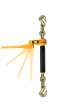
My question is, if I buy something like this - https://www.stevenstractor.com/home...l length is 4-5/16 with 5/8 thread dia..html - and secure it to the ball in the right-side upper lift arm, and then attach the leveling box to it, will that cause any problems? Is there a "right way" to convert my B2650 from "ball in the upper lift arm" to "pin in the upper lift arm?"

Thanks!
 

TheOldHokie

Well-known member
Lifetime Member

Equipment
L3901/LA525, B7200DT/B1630, G2160/RCK60, G2460/RCK60
Apr 6, 2021
6,667
3,214
113
Myersville, MD
windyridgefarm.us
I have a B2650. I stumbled across this video -
- the other day, and as I have some sloped grading to do with my box blade, I was intrigued. I'd not heard of a leveling box before this video, just TnT. And TnT is overkill for my needs so I decided to give this a go on a whim.

I stupidly thought all Cat 1 3-points are the same, and didn't realize that where the top of this setup is designed to fit over a pin (which the guy in the video says is a standard 3/4" for Cat 1), my current leveling arm has yokes designed for 5/8" pins top and bottom, and the upper lift arms (connected to the rock shaft) have balls with 5/8" ID.

So, it seems like there are at least two kinds of Cat 1 setups. One like I have, with the balls in the upper lift arms using a 5/8" pin, and one like others have, with 3/4" pins on the upper lift arms and leveling arms/sidelinks designed to fit over and secure with a lynch pin.

My question is, if I buy something like this - https://www.stevenstractor.com/home/3/4" pin dia, 1-5/8 usable length, overall length is 4-5/16 with 5/8 thread dia..html - and secure it to the ball in the right-side upper lift arm, and then attach the leveling box to it, will that cause any problems? Is there a "right way" to convert my B2650 from "ball in the upper lift arm" to "pin in the upper lift arm?"

Thanks!
A gear driven leveling box is pretty standard and I don't know why Kubota cheaps out with the turnbuckle style side link. Well, maybe I do know.....

The Category X pin sizes are only standardized at the 3pt implement attachment point. Pin sizes and types in the associated linkage are left to the tractor designer.

Depending on the geometry of your lift arm you might want to consider something like the yoke arrangement shown below. It will add to the length of the side link so take that into consideration

Dan

1654771838076.png
 
Last edited:

mculik5

Member

Equipment
B2650 TLB
Sep 22, 2020
32
5
8
NJ
@TheOldHokie - Thanks!

In furtherance of the idea that I'm an idiot, I realized after posting that the pin hole attachment on the leveling box is, itself, pinned to a yoke on the leveling box using a 3/4" pin. So, I removed the pin and bought some 3/4" x 5/8" bushings to step the holes down, along with a longer 5/8" pin and am hoping I can use it that way. It definitely looks like it will work, but...famous last words... The parts should be here today, so I'll post later how it goes.
 
  • Like
Reactions: 1 user

radas

Well-known member

Equipment
2022 LX2610HST, 3rd Function, Rear Remotes, BH77
Mar 21, 2022
721
831
93
Michigan
@TheOldHokie - Thanks!

In furtherance of the idea that I'm an idiot, I realized after posting that the pin hole attachment on the leveling box is, itself, pinned to a yoke on the leveling box using a 3/4" pin. So, I removed the pin and bought some 3/4" x 5/8" bushings to step the holes down, along with a longer 5/8" pin and am hoping I can use it that way. It definitely looks like it will work, but...famous last words... The parts should be here today, so I'll post later how it goes.
He's got an L series unit in his video, is the link posted in his video compatible with the B2650? I have an LX (same as your B) and this is a much more affordable option vs full top and tilt.
 

mculik5

Member

Equipment
B2650 TLB
Sep 22, 2020
32
5
8
NJ
@TheOldHokie, @radas - No go tonight. The parts came and work/fit, but the crank handle hits my backhoe subframe and ROPs or, if I turn it the other way, the top link and PTO shaft guard. I tried to make a video, but I had the camera resting on the folded ROPS and kept sticking my head in the way. Will ask my wife to hold the camera tomorrow so I can show you exactly what I mean.

Long story short, I think the only way to make it fit right is to fabricate a yoke so that the crank handle is where it's supposed to be, not turned 90 degrees.

Also, although the whole setup seemed to move up and down smoothly without any binding, the ball in my upper lift arm (connected to rock shaft) where I had the leveling box connected got jammed and was then really tight (whereas it was very free-moving before I hooked the leveling box up).

Not giving up. More to come...
 
  • Sad
Reactions: 1 user

radas

Well-known member

Equipment
2022 LX2610HST, 3rd Function, Rear Remotes, BH77
Mar 21, 2022
721
831
93
Michigan
@TheOldHokie, @radas - No go tonight. The parts came and work/fit, but the crank handle hits my backhoe subframe and ROPs or, if I turn it the other way, the top link and PTO shaft guard. I tried to make a video, but I had the camera resting on the folded ROPS and kept sticking my head in the way. Will ask my wife to hold the camera tomorrow so I can show you exactly what I mean.

Long story short, I think the only way to make it fit right is to fabricate a yoke so that the crank handle is where it's supposed to be, not turned 90 degrees.

Also, although the whole setup seemed to move up and down smoothly without any binding, the ball in my upper lift arm (connected to rock shaft) where I had the leveling box connected got jammed and was then really tight (whereas it was very free-moving before I hooked the leveling box up).

Not giving up. More to come...
Thanks for the update! Regarding the binding, do you think it's because the min/max range on the adjustable link is greater than the factory? Or was the angle slightly different?
 

TheOldHokie

Well-known member
Lifetime Member

Equipment
L3901/LA525, B7200DT/B1630, G2160/RCK60, G2460/RCK60
Apr 6, 2021
6,667
3,214
113
Myersville, MD
windyridgefarm.us
@TheOldHokie, @radas - No go tonight. The parts came and work/fit, but the crank handle hits my backhoe subframe and ROPs or, if I turn it the other way, the top link and PTO shaft guard. I tried to make a video, but I had the camera resting on the folded ROPS and kept sticking my head in the way. Will ask my wife to hold the camera tomorrow so I0 can show you exactly what I mean.

Long story short, I think the only way to make it fit right is to fabricate a yoke so that the crank handle is where it's supposed to be, not turned 90 degrees.

Also, although the whole setup seemed to move up and down smoothly without any binding, the ball in my upper lift arm (connected to rock shaft) where I had the leveling box connected got jammed and was then really tight (whereas it was very free-moving before I hooked the leveling box up).

Not giving up. More to come...
If I understood your previous post you removed the block that came on the end if the leveling box. That block turns the crank handle up and acts as a universal joint to help prevent binding. The geometry of the OEM side links is bent at an angle which you are probably going to have to match with your yoke. Links on B series machines are also pretty small/light which complicates using those aftermarket parts. I bought replacement links (both sides) for my B7200 from Weaver and it took some tweaking to get them to fit.

Dan
 

wendol

Active member
Lifetime Member

Equipment
L3800 HST
Feb 5, 2014
190
37
28
80
North Tx
I've explored the idea (without success this far) of trying to convert this leveling box to that of a ratchet style with folding handle............similar to the concept used in this binder.

Your thoughts????
 

Attachments

mculik5

Member

Equipment
B2650 TLB
Sep 22, 2020
32
5
8
NJ
As promised, here's a link to a video showing the situation.


@TheOldHokie - You're spot on.
@radas - I'm not sure about the binding. It didnt' seem to bind to me, but clearly something I did messed the ball up.
@wendol - I really like that idea. Could you cut the ends off of a binder and weld yokes on...? My welding skills aren't at the level where I'd trust myself doing something like that.

Also, I measured the OE non-adjustable link and modeled both it and leveling box in CAD and then drew a really quick possible solution, but I haven't spent any time refining it. I used the non-adjustable link because that would be the length needed to be level on the leveling box.

Unfortunately, on the B-Series, it seems that the minimum length of the leveling box is also level, meaning the implement can only tilt from level down, not also from level up.

I may 3D-print my rough fix to see if the geometry works. If I do, I'll make another video.

NOTE: The OE link is in red, the leveling box is in green, and my new part is blue. The pin holes on both units are how they are aligned with each other.

1654912669909.png
 

mculik5

Member

Equipment
B2650 TLB
Sep 22, 2020
32
5
8
NJ
Tonight's update...some progress...

I've got a revised part printing right now. We'll see how it does tomorrow.

 
  • Like
Reactions: 1 user

radas

Well-known member

Equipment
2022 LX2610HST, 3rd Function, Rear Remotes, BH77
Mar 21, 2022
721
831
93
Michigan
Tonight's update...some progress...

I've got a revised part printing right now. We'll see how it does tomorrow.

Thanks for sharing your progress. Look forward to seeing what you come up with in the 2nd iteration.
 

mculik5

Member

Equipment
B2650 TLB
Sep 22, 2020
32
5
8
NJ
Did a bunch of poking around yesterday (Sunday) and believe I've landed on a part that could work. See the screenshot below. More details below the screenshot.

1655148008617.png


The issue I was running into with my previous designs is that weight on the lower lift arm (red vertical arrow) would transfer sideways (red horizontal arrow) and, because of the ball joint in the upper lift arm, pull the part as low as possible until the back of the part hit the top of the upper lift arm. In most cases, it would hit in the vicinity of the blue arrow.

So, what was needed was a part design that would prevent the the upper part of the leveling box from descending below a certain point that would cause the lower lift arms to be level at about midway through the leveling box's travel.

The part above is designed to hit the leveling box in the area circled in yellow. In order for the top part of the leveling box to descend lower, the part needs to rotate downward, which it can't do because there's no clearance in the area circled in yellow. However, because there IS clearance on the other side, it can rotate the other direction as the 3PT is lifted.

This design also keeps the pin tabs that go over the upper lift arm relatively centered and the ball at a reasonable, although not perfectly straight, angle. I'm no mechanical engineer, but I also think this setup is better about not pulling the two pin tabs apart like the other designs.

I did print this part and test it, and it worked. The 3PT raised and lowered with no binding, and it only went as low as the other lift arm. Although it's tight to the upper lift arm, I didn't initially observe it hitting them. Additionally, this has the lift arms level at almost dead on the middle of the leveling box's travel, meaning I can go 2.25" down and 2" up (which obviously translates to much more movement at the edge of a 5' box blade or rake).

The reason I don't have a video is because it worked well enough that I decided to stand on my lift arms to test it further and promptly broke the plastic.

The only potential issue I noticed is that, at some point, it contacted the upper lift arm, again by the blue arrow above. This happened while I had my weight on it, but I'm not sure if it happened before or after breaking. The other, bigger issue is whether the top of the leveling box will hold up to the weight of implements pressing on it through this part, especially as they bounce as you drive with them in the air.

At this point, I'm going to try to design a part with the same geometry using square tube that I can weld. If that doesn't seem to work well, I'll probably have some parts laser cut and weld them up from there. I did some online instant CNC quotes, but they were in the neighborhood of $300-$400, which isn't worth it.

Would love your feedback, good and bad. Thanks!
 

radas

Well-known member

Equipment
2022 LX2610HST, 3rd Function, Rear Remotes, BH77
Mar 21, 2022
721
831
93
Michigan
Did a bunch of poking around yesterday (Sunday) and believe I've landed on a part that could work. See the screenshot below. More details below the screenshot.

View attachment 81762

The issue I was running into with my previous designs is that weight on the lower lift arm (red vertical arrow) would transfer sideways (red horizontal arrow) and, because of the ball joint in the upper lift arm, pull the part as low as possible until the back of the part hit the top of the upper lift arm. In most cases, it would hit in the vicinity of the blue arrow.

So, what was needed was a part design that would prevent the the upper part of the leveling box from descending below a certain point that would cause the lower lift arms to be level at about midway through the leveling box's travel.

The part above is designed to hit the leveling box in the area circled in yellow. In order for the top part of the leveling box to descend lower, the part needs to rotate downward, which it can't do because there's no clearance in the area circled in yellow. However, because there IS clearance on the other side, it can rotate the other direction as the 3PT is lifted.

This design also keeps the pin tabs that go over the upper lift arm relatively centered and the ball at a reasonable, although not perfectly straight, angle. I'm no mechanical engineer, but I also think this setup is better about not pulling the two pin tabs apart like the other designs.

I did print this part and test it, and it worked. The 3PT raised and lowered with no binding, and it only went as low as the other lift arm. Although it's tight to the upper lift arm, I didn't initially observe it hitting them. Additionally, this has the lift arms level at almost dead on the middle of the leveling box's travel, meaning I can go 2.25" down and 2" up (which obviously translates to much more movement at the edge of a 5' box blade or rake).

The reason I don't have a video is because it worked well enough that I decided to stand on my lift arms to test it further and promptly broke the plastic.

The only potential issue I noticed is that, at some point, it contacted the upper lift arm, again by the blue arrow above. This happened while I had my weight on it, but I'm not sure if it happened before or after breaking. The other, bigger issue is whether the top of the leveling box will hold up to the weight of implements pressing on it through this part, especially as they bounce as you drive with them in the air.

At this point, I'm going to try to design a part with the same geometry using square tube that I can weld. If that doesn't seem to work well, I'll probably have some parts laser cut and weld them up from there. I did some online instant CNC quotes, but they were in the neighborhood of $300-$400, which isn't worth it.

Would love your feedback, good and bad. Thanks!
If you are ok sharing the DXF, I can check with my buddy who owns a mfg. facility and contracts with laser shop at a large scale to see if he can get quotes. If you are not comfortable sharing, no worries.
 

TheOldHokie

Well-known member
Lifetime Member

Equipment
L3901/LA525, B7200DT/B1630, G2160/RCK60, G2460/RCK60
Apr 6, 2021
6,667
3,214
113
Myersville, MD
windyridgefarm.us
Did a bunch of poking around yesterday (Sunday) and believe I've landed on a part that could work. See the screenshot below. More details below the screenshot.

View attachment 81762

The issue I was running into with my previous designs is that weight on the lower lift arm (red vertical arrow) would transfer sideways (red horizontal arrow) and, because of the ball joint in the upper lift arm, pull the part as low as possible until the back of the part hit the top of the upper lift arm. In most cases, it would hit in the vicinity of the blue arrow.

So, what was needed was a part design that would prevent the the upper part of the leveling box from descending below a certain point that would cause the lower lift arms to be level at about midway through the leveling box's travel.

The part above is designed to hit the leveling box in the area circled in yellow. In order for the top part of the leveling box to descend lower, the part needs to rotate downward, which it can't do because there's no clearance in the area circled in yellow. However, because there IS clearance on the other side, it can rotate the other direction as the 3PT is lifted.

This design also keeps the pin tabs that go over the upper lift arm relatively centered and the ball at a reasonable, although not perfectly straight, angle. I'm no mechanical engineer, but I also think this setup is better about not pulling the two pin tabs apart like the other designs.

I did print this part and test it, and it worked. The 3PT raised and lowered with no binding, and it only went as low as the other lift arm. Although it's tight to the upper lift arm, I didn't initially observe it hitting them. Additionally, this has the lift arms level at almost dead on the middle of the leveling box's travel, meaning I can go 2.25" down and 2" up (which obviously translates to much more movement at the edge of a 5' box blade or rake).

The reason I don't have a video is because it worked well enough that I decided to stand on my lift arms to test it further and promptly broke the plastic.

The only potential issue I noticed is that, at some point, it contacted the upper lift arm, again by the blue arrow above. This happened while I had my weight on it, but I'm not sure if it happened before or after breaking. The other, bigger issue is whether the top of the leveling box will hold up to the weight of implements pressing on it through this part, especially as they bounce as you drive with them in the air.

At this point, I'm going to try to design a part with the same geometry using square tube that I can weld. If that doesn't seem to work well, I'll probably have some parts laser cut and weld them up from there. I did some online instant CNC quotes, but they were in the neighborhood of $300-$400, which isn't worth it.

Would love your feedback, good and bad. Thanks!
I don't see that as a laser cut part. I use OSHcut and they are reasonable but small/single quantities are a killer. I have a local company that is a lot cheaper for one offs.

Dan
 

rswilliams

New member
Lifetime Member

Equipment
LX2610
Jul 5, 2022
8
2
3
Signal Mountain, TN
There is a Kubota Part No. B2667 that is a ratcheting leveling box that Watershed Overlook (YouTube Name) used on his LX2610. I have been wanting to pull a trigger for it but I can not find a picture to know exactly what it is. In the notes on his video he comments on some discrepancy in the part numbers.

If this works on an LX it should work on a B.
 

radas

Well-known member

Equipment
2022 LX2610HST, 3rd Function, Rear Remotes, BH77
Mar 21, 2022
721
831
93
Michigan
There is a Kubota Part No. B2667 that is a ratcheting leveling box that Watershed Overlook (YouTube Name) used on his LX2610. I have been wanting to pull a trigger for it but I can not find a picture to know exactly what it is. In the notes on his video he comments on some discrepancy in the part numbers.

If this works on an LX it should work on a B.
I was debating on pulling the trigger on that but saw some feedback on TBN where the ratcheting mechanism on those were breaking relatively quickly. Doesn't seem like it happens to all units but something to consider.
 

Matt Ellerbee

Well-known member
Lifetime Member

Equipment
MX6000
Jun 27, 2019
1,654
1,859
113
Canton, Georgia
There is a Kubota Part No. B2667 that is a ratcheting leveling box that Watershed Overlook (YouTube Name) used on his LX2610. I have been wanting to pull a trigger for it but I can not find a picture to know exactly what it is. In the notes on his video he comments on some discrepancy in the part numbers.

If this works on an LX it should work on a B.
This is the ratcheting link.
Screenshot 2022-09-01 121404.png