I need of instruction on how to properly assemble a zextel inline 3 injector pump. I have a generic diagram but it is not sufficient. I do not seem to be installing the valveing at the right degree / angle because I have no fuel control. Casting number 63001 86723 . also (16030 STOP ->) ( on the other side.) 1996 ish model year
assemble zextel 3 cyl inj pump
- Thread starter kadilacdan
- Start date
kadilacdan
I just successfully rebuild a zexel injection pump.
Here is a link to my thread http://www.orangetractortalks.com/forums/showthread.php?t=21710&highlight=b7100
There are markings for the plunger and the cylinder can only go in one way. Review the thread and let me know where you are getting stuck.
After you put the pump in, it takes a while to get fuel flowing again. Use decompression lever and do not burn up your starter. I have a commercial grade battery charger jumper so the battery would not get warn down.
Last edited:
Thank you. My pump is mildly different and am only assuming that my assembly is at fault. the only thing I can see as a variable is the one pin that can go in one of two ways. I don't know which is correct.
Attachments
-
 93.3 KB Views: 533
Your pump is indeed different. However, the basic principles of operation have to be the same.
I started with the rack in the pump and installed one at a time. The control sleeve timing to the rack is critical. That is the first thing I inserted - the control sleeve and made triple sure that the notch and timing mark were lined up.
If you say this part can go in the correct way or be a 180 degrees off, then you may have to go through the trouble of installing one way and then the other way. Dont forget that it takes forever to get fuel to flow. When I got my pump together, one of the cylinders was not pumping fuel and I almost pulled the pump out. Be patient.
After I got the control sleeve in (is this what you are referring to as the pin?), I installed the plunger cylinder. On my pump, the control sleeve went in from the bottom and the plunger cylinder went in from the top. There is a notch on the control sleeve and a line on the plunger that line up! Another way to check the plunger to the cylinder is that the slash cut on the plunger generally faces the hole in the plunger cylinder. Recall that the plunger cylinder can only go in one way.
All of the stuff has markings and at first I did not know of the markings so it made no sense. Once you figure out the markings, it will work.
Here is a video I watched that was a motivator for me. The pump is not your pump but it may be worth a watch.
https://www.youtube.com/watch?v=o9SFdAxf1Fc
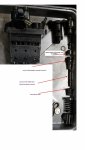
1) Could you post a couple close up photos of the rack and the control sleeve (pin - I think its the piece above the spring, first red arrow from the bottom in your image).
2) When you put your delivery valve in and screw down the delivery valve holder, does the holder go all the way? There should be no threads showing or very little.
I started with the rack in the pump and installed one at a time. The control sleeve timing to the rack is critical. That is the first thing I inserted - the control sleeve and made triple sure that the notch and timing mark were lined up.
If you say this part can go in the correct way or be a 180 degrees off, then you may have to go through the trouble of installing one way and then the other way. Dont forget that it takes forever to get fuel to flow. When I got my pump together, one of the cylinders was not pumping fuel and I almost pulled the pump out. Be patient.
After I got the control sleeve in (is this what you are referring to as the pin?), I installed the plunger cylinder. On my pump, the control sleeve went in from the bottom and the plunger cylinder went in from the top. There is a notch on the control sleeve and a line on the plunger that line up! Another way to check the plunger to the cylinder is that the slash cut on the plunger generally faces the hole in the plunger cylinder. Recall that the plunger cylinder can only go in one way.
All of the stuff has markings and at first I did not know of the markings so it made no sense. Once you figure out the markings, it will work.
Here is a video I watched that was a motivator for me. The pump is not your pump but it may be worth a watch.
https://www.youtube.com/watch?v=o9SFdAxf1Fc
1) Could you post a couple close up photos of the rack and the control sleeve (pin - I think its the piece above the spring, first red arrow from the bottom in your image).
2) When you put your delivery valve in and screw down the delivery valve holder, does the holder go all the way? There should be no threads showing or very little.
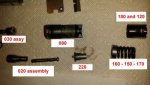
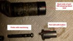
OK so here is what I have. Pin /button is on part 220. I guess what I really need to know then is the installation orientation of part assembly 020. Thanks again for all the insight. Daniel
Attachments
-
 33.2 KB Views: 5,363
 -
 19.7 KB Views: 868
 -
 67.1 KB Views: 816
 -
 14.4 KB Views: 746
 -
 12.8 KB Views: 710
Daniel:
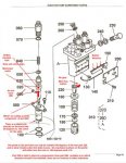
what you are calling the pintle is the plunger which goes into the cylinder. These two pieces (No 20 in the diagram) are what experience wear and get replaced. The other pieces that get replaced are the delivery valves (No 30 in the diagram). The delivery valve sits on top of the cylinder.
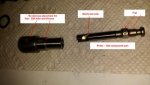
The timing in your pump is simplified as the "buttons" on No 220 go into the "notches" on No 190, the rack . CAREFULLY examine the plunger and No 220. The plunger, shown in your image No 5 (last image) has flat parts and go into No 220. There should be a notch on 220 (the bottom part) and a line on the plunger that line up. The flat part (image 5) goes into No 220 and gets rotated by the rack to deliver more or less fuel. The plunger is kept in place by No 170.
No 20 does not go in as one piece. THE CYLINDER GOES IN FROM THE TOP and THE PLUNGER GOES IN FROM THE BOTTOM and is kept in place by No 170.
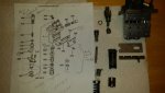
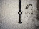
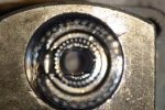
Im attaching images which show the line on the plunger and the notch on what would be No 220 (the control sleeve). The image is of the control sleeve in the pump. It is blurry but its for illustration purposes. The notch is on the bottom of the control sleeve and there should also be one on No 220. The notch is on the bottom of the control sleeve and is at 3pm on the second image.
On my pump, the slash on the plunger faced AWAY FROM the rack, AWAY from the side of the pump (No 230 in your diagram) that delivered the fuel. Similarly, the cylinder hole and machined notch (top part of No. 20) also faced AWAY from the part of the pump that delivered fuel. IS IT POSSIBLE that the missing part No 90 is part of No 80? Carefully check to see how the cylinder (the top part of No 20) goes into No 80. There should be only one way for the cylinder to go into No 80.
This is a guess but could you be rotating No 80 by 180 degrees and therefore putting in the cylinder hole and machined slash cut the wrong way.
Assemble the top of the pump first, including delivery valves and holders. Then insert the plungers, lower spring seats and tappets from the bottom.
Reread this as I have several edits. Feel free to send me a private message so we can talk on the phone. Good luck!!
what you are calling the pintle is the plunger which goes into the cylinder. These two pieces (No 20 in the diagram) are what experience wear and get replaced. The other pieces that get replaced are the delivery valves (No 30 in the diagram). The delivery valve sits on top of the cylinder.
The timing in your pump is simplified as the "buttons" on No 220 go into the "notches" on No 190, the rack . CAREFULLY examine the plunger and No 220. The plunger, shown in your image No 5 (last image) has flat parts and go into No 220. There should be a notch on 220 (the bottom part) and a line on the plunger that line up. The flat part (image 5) goes into No 220 and gets rotated by the rack to deliver more or less fuel. The plunger is kept in place by No 170.
No 20 does not go in as one piece. THE CYLINDER GOES IN FROM THE TOP and THE PLUNGER GOES IN FROM THE BOTTOM and is kept in place by No 170.
Im attaching images which show the line on the plunger and the notch on what would be No 220 (the control sleeve). The image is of the control sleeve in the pump. It is blurry but its for illustration purposes. The notch is on the bottom of the control sleeve and there should also be one on No 220. The notch is on the bottom of the control sleeve and is at 3pm on the second image.
On my pump, the slash on the plunger faced AWAY FROM the rack, AWAY from the side of the pump (No 230 in your diagram) that delivered the fuel. Similarly, the cylinder hole and machined notch (top part of No. 20) also faced AWAY from the part of the pump that delivered fuel. IS IT POSSIBLE that the missing part No 90 is part of No 80? Carefully check to see how the cylinder (the top part of No 20) goes into No 80. There should be only one way for the cylinder to go into No 80.
This is a guess but could you be rotating No 80 by 180 degrees and therefore putting in the cylinder hole and machined slash cut the wrong way.
Assemble the top of the pump first, including delivery valves and holders. Then insert the plungers, lower spring seats and tappets from the bottom.
Reread this as I have several edits. Feel free to send me a private message so we can talk on the phone. Good luck!!
Attachments
-
 94.7 KB Views: 394
 -
 20.3 KB Views: 399
Last edited:
Re: assemble zextel 3 cyl inj pump Solved
 Thank you The Pump Guy, TPG!! thepumpguysc@aol.com
I was close to the solution but followed TPG's instruction. TPG came through and confirmed it. I recommend and will definitely use his services!!
The pump Guy (thepumpguysc@aol.com) hooked me up to get her running. When I'm done proving the engine I will send him the pump to rebuild. She runs good but is not calibrated. His answer below.
With TPG's permission I give him a plug.
(TPG) "The problem is.. your missing 090.. its a small assembly pin that centers the barrel into the flange for proper alignment.. and it goes away from the rack.. along with the plunger."
(Me)I have no pins and my barrels were in all different directions.
(TPG) "The plungers go in.. slot/helix opposite the rack.. and MUST move freely, with the slightest touch of the rack"
(Me)The grove in the barrel also faces away from the rack, and is aligned with the pin, which in my case is only used during assembly, which was my problem.
(TPG) "Once you loosen the top nut on those pumps and they don't have a pin in it, your screwed..!!!
OR if it HAD a pin in it..once you remove the barrel, the pin falls out and your screwed.."
(Me) In my application I used a .08 drill bit ..
(TPG) "just swap it from 1 to the other (drill bit/pin), AFTER tightening the top nut [delivery valve holder] to 30-35 ft lbs..
The only problem I see with that is>> you see the flange is slotted, where it tightens into the main housing.. with 2 screws.???
THATS the EQUAL DELIVERY setting for EACH cylinder.. if you don't have that set correct.. the engine is going to skip BAD..!!!
That's why I have a 85K $ test stand to run them on..
Thank you TPG awesome help and great service.
Daniel Kozak
Social Circle, GA
Thank you The Pump Guy, TPG!! thepumpguysc@aol.comI was close to the solution but followed TPG's instruction. TPG came through and confirmed it. I recommend and will definitely use his services!!
The pump Guy (thepumpguysc@aol.com) hooked me up to get her running. When I'm done proving the engine I will send him the pump to rebuild. She runs good but is not calibrated. His answer below.
With TPG's permission I give him a plug.
(TPG) "The problem is.. your missing 090.. its a small assembly pin that centers the barrel into the flange for proper alignment.. and it goes away from the rack.. along with the plunger."
(Me)I have no pins and my barrels were in all different directions.
(TPG) "The plungers go in.. slot/helix opposite the rack.. and MUST move freely, with the slightest touch of the rack"
(Me)The grove in the barrel also faces away from the rack, and is aligned with the pin, which in my case is only used during assembly, which was my problem.
(TPG) "Once you loosen the top nut on those pumps and they don't have a pin in it, your screwed..!!!
OR if it HAD a pin in it..once you remove the barrel, the pin falls out and your screwed.."
(Me) In my application I used a .08 drill bit ..
(TPG) "just swap it from 1 to the other (drill bit/pin), AFTER tightening the top nut [delivery valve holder] to 30-35 ft lbs..
The only problem I see with that is>> you see the flange is slotted, where it tightens into the main housing.. with 2 screws.???
THATS the EQUAL DELIVERY setting for EACH cylinder.. if you don't have that set correct.. the engine is going to skip BAD..!!!
That's why I have a 85K $ test stand to run them on..
Thank you TPG awesome help and great service.
Daniel Kozak
Social Circle, GA