Hello to all,
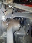
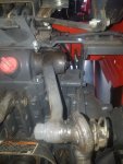
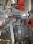
I am new to the forum, so please forgive my errors, and thanks in advance for any advice. I have a L4600DT with 140 hrs. I noticed during my maintenance when I applied grease to the right hydraulic lift arm that the grease was just shooting out of the splines instead of the other end of the shaft between the arm and chassis. The spline shaft is sticking out about 1/8" past the end of the lift arm. My question: Is that normal, and if not, is it an o-ring issue or could there be something wrong with the shaft? How hard is it to remove the shaft, and does anyone know of a video to how to do repairs? Sorry it is so wordy.
I am new to the forum, so please forgive my errors, and thanks in advance for any advice. I have a L4600DT with 140 hrs. I noticed during my maintenance when I applied grease to the right hydraulic lift arm that the grease was just shooting out of the splines instead of the other end of the shaft between the arm and chassis. The spline shaft is sticking out about 1/8" past the end of the lift arm. My question: Is that normal, and if not, is it an o-ring issue or could there be something wrong with the shaft? How hard is it to remove the shaft, and does anyone know of a video to how to do repairs? Sorry it is so wordy.