During colder temperatures I never had confidence my L4740-3 tractor would start. Sometimes multiple glow plug cycles would be needed and very long crank times. Nothing seemed to help which led to a hunt to find the root cause. This did not come easy and required a fairly long period of time to uncover.
Please note the glow plug on time is regulated by the ECU based on coolant temperature for this Grand L series. (User has no control over how long GP remains energized)
Figuring it was fuel related, the entire contents of the fuel tank was drained and replaced with fuel from a high volume truck stop along with added fuel treatment (Power Service white bottle). Fuel delivery on the output side of filter was strong and continuous.
Glow Plug Relay was verified to be functioning correctly by testing the resistance values and by a bench test using a battery and an old headlight. Also tried swapping with the other relay plus a newly purchased spare relay with same hard to starting results. (All relays verified good before installing).
Verified battery voltage was present when commanded by the ECU to the control side of relay. Note: GP indicator light illuminates for varying times in the intellipanel.
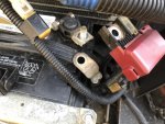
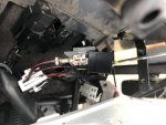
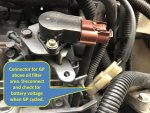
Verified battery voltage present at the glow plug buss bar. There is a white connector above the fuel filter that can be removed to easily check supply voltage on this model.
Verified battery was fully charged also Load tested and found to be OK.
Tested glow plugs resistance and found to be ok. Even removed all four plugs and tested them on the bench to make certain they all began to glow similar to each other. It only takes about 4 seconds for them to become red hot. In 10 seconds they are almost white hot. They heat up amazingly fast and stay red hot once power is removed.
In other words the easy stuff was checked and verified and I was very puzzled why it was so difficult to start when voltage was present at the glow plugs.
One cold day the tractor would not start, so I made up a jumper wire and applied battery voltage to the GP buss bar wire connector near the fuel filter (See photo). Applied voltage for 10 seconds and my wife engaged starter. The tractor started before the engine turned one revolution!!! How can this be?
Not trusting the results waited until the next morning when it was cold and tried it again. Tractor would not start using stock circuit, but when using the jumper wire to the GP buss bar it would start immediately. Confirmation!
So my electrical system is not capable of delivering the necessary current for Glow Plug operation.
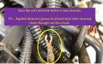
Decided to start at the battery and disassemble and clean every wire termination to bare metal within the GP circuit. After completing each section a start attempt was made. Note: Dielectric grease was used after cleaning each connection.
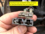
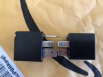
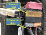
It is not sufficient to only clean the battery terminal and wire, but the assembly that makes up the High Current Fuses. (see photos)
Removed the buss bar and wire termination cleaning all contact points. Still would not start.
The only place left in the circuit is the relay socket itself.
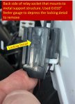
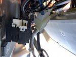
First off the relay socket needs to be removed from the mounting detail. This was accomplished by inserting a 0.010" feeler gauge between the metal and plastic. Jiggle from side to side while push down and it will eventually release the relay socket.
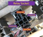
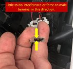
The relay insertion and extraction feels like there is good terminal grip, so I used 1/4" male connectors to test each female connector independently within the relay socket. The two pins for the control side (Low current small diameter wire) are tight with good friction. The power side is loose and the 1/4" male tab just slips right in. WOW this could be the problem.
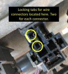
To remove the female wire terminals from within the housing requires the housing to be disassembled. Start by removing the white plastic wire holder by gently prying on the tabs while pushing downward. Then two small screwdrivers (kind use for eyeglasses) can be used to unclip the female terminal from the black housing.
The power side female terminals are designed for 3/8" male tabs. When the relay tab is inserted there is no appreciable amount of grip. It is as if the spring detail within the female tab is fatigued. Tried bending, but it will not hold its position once the male tab is inserted.
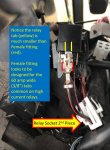
Higher current relays (60 amps and above) can be purchased with power side tabs that are 3/8" wide. More importantly these are 50% thicker than the 1/4" male tabs on found on the stock 40 amp relay. (0.045" vs 0.030").
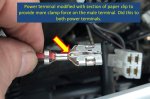
Not having one of these relays available and having to travel for work while others needed the tractor, the female terminal was modified using a standard size paper clip.
The paper clip was cut and bent into a simple u-shape and inserted into the wire terminal as shown in the photo. It is not ideal, but works in providing the proper tension to carry the current.
Once modified and reassembled the tractor starts very quickly (less than two revolutions of the motor). So quickly is all I want to do is start it and be amazed at how quickly it now starts.
A better and easier solution might be to use a relay the socket is actually designed to accept and NOT what Kubota uses. Many 60 amp and higher relays will have the larger tabs.
The higher current rating is not needed, only the larger thicker male tabs. If the female tabs inside the relay socket are fatigued (speculating from high heat due to the poor connection) the larger male tabs might still not be enough. It is a real pain to take the relay socket apart so I'd consider the relay option as a first attempt, but maybe not the solution in all cased.
Misc:
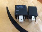
The stock Panasonic relay from Kubota is nothing special although it is sealed. No diodes, resistors, etc. to suppress voltage spikes when the field is collapsed. (Went through the effort to decode the part number on Panasonic's web site and relay technical info.) The stock relay, Panasonic CB-1a-12V ACB33201 utilizes four - 1/4" female tabs with the following dimensions: 0.250 wide by 0.030" thick.
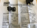
Purchased two new 80 amp relays with the larger 3/8" tabs for the power side of the relay. 80 amps is overkill, but that is what I bought off amazon. Picker PC795-1A-C-12S-RN-X at $18.99 for the pair. They are sealed units, with nickel plated tabs and a resistor to protect the voltage spike that occurs when the field collapses. The new relay has two-1/4" and two-3/8" tabs that measure 0.368" wide and 0.045 thick. Note: Measurements taken with Starrett dial calipers. Here's a link to the relays if anyone is interested.
https://www.amazon.com/gp/product/B07GX6SXY2/ref=ox_sc_act_title_1?smid=A16HAOC7J321VG&psc=1
The thicker tabs should work significantly better with the mating female electrical connectors as they are designed for the wider male tabs.
The same relay and mating socket are used for another circuit that I believe controls circuits that can prevent the tractor from starting so plan on using one of the relays in this circuit even though it is not causing any issues at this point. (My tractor would not start with the relay missing)
The larger plastic housing of the 80 amp relay does NOT create a fit issue. There is plenty of room to accommodate the relay.
Kubota does sell a similar relay with their expected markup over what's available on the open market.
Glow Plug info
All four Glow Plugs can be removed without removing anything besides the buss bar on my tractor.
Glow Plugs: 19077-65512, 19077-65511, 19077-65510, 1J860-65510, 1J860-65510, 1J860-65511, 1J860-65512 are all linked as similar using Kubota's Illustrated Parts and Messick's web sites.
GP price is different depending on PN. Surprising given they are functionally the same or at least interchangeable based on what I've found.
Kubota 19077-65512 is actually a NGK Glow Plug Part number: Y-716RS, stock number: 4693 (Rockauto has them for <$15) NGK and PN are stamped right on the GP.
GP Nut size: 7mm for buss bar
GP itself: 12mm (deep socket)
NGK Data: https://www.ngkpartfinder.co.uk/files/NGK_Glow-Spec.pdf
Hopefully the pictures will help clarify the above and if there are any questions please ask away.
Personally I think Kubota dropped the ball on this.
Please note the glow plug on time is regulated by the ECU based on coolant temperature for this Grand L series. (User has no control over how long GP remains energized)
Figuring it was fuel related, the entire contents of the fuel tank was drained and replaced with fuel from a high volume truck stop along with added fuel treatment (Power Service white bottle). Fuel delivery on the output side of filter was strong and continuous.
Glow Plug Relay was verified to be functioning correctly by testing the resistance values and by a bench test using a battery and an old headlight. Also tried swapping with the other relay plus a newly purchased spare relay with same hard to starting results. (All relays verified good before installing).
Verified battery voltage was present when commanded by the ECU to the control side of relay. Note: GP indicator light illuminates for varying times in the intellipanel.
Verified battery voltage present at the glow plug buss bar. There is a white connector above the fuel filter that can be removed to easily check supply voltage on this model.
Verified battery was fully charged also Load tested and found to be OK.
Tested glow plugs resistance and found to be ok. Even removed all four plugs and tested them on the bench to make certain they all began to glow similar to each other. It only takes about 4 seconds for them to become red hot. In 10 seconds they are almost white hot. They heat up amazingly fast and stay red hot once power is removed.
In other words the easy stuff was checked and verified and I was very puzzled why it was so difficult to start when voltage was present at the glow plugs.
One cold day the tractor would not start, so I made up a jumper wire and applied battery voltage to the GP buss bar wire connector near the fuel filter (See photo). Applied voltage for 10 seconds and my wife engaged starter. The tractor started before the engine turned one revolution!!! How can this be?
Not trusting the results waited until the next morning when it was cold and tried it again. Tractor would not start using stock circuit, but when using the jumper wire to the GP buss bar it would start immediately. Confirmation!
So my electrical system is not capable of delivering the necessary current for Glow Plug operation.
Decided to start at the battery and disassemble and clean every wire termination to bare metal within the GP circuit. After completing each section a start attempt was made. Note: Dielectric grease was used after cleaning each connection.
It is not sufficient to only clean the battery terminal and wire, but the assembly that makes up the High Current Fuses. (see photos)
Removed the buss bar and wire termination cleaning all contact points. Still would not start.
The only place left in the circuit is the relay socket itself.
First off the relay socket needs to be removed from the mounting detail. This was accomplished by inserting a 0.010" feeler gauge between the metal and plastic. Jiggle from side to side while push down and it will eventually release the relay socket.
The relay insertion and extraction feels like there is good terminal grip, so I used 1/4" male connectors to test each female connector independently within the relay socket. The two pins for the control side (Low current small diameter wire) are tight with good friction. The power side is loose and the 1/4" male tab just slips right in. WOW this could be the problem.
To remove the female wire terminals from within the housing requires the housing to be disassembled. Start by removing the white plastic wire holder by gently prying on the tabs while pushing downward. Then two small screwdrivers (kind use for eyeglasses) can be used to unclip the female terminal from the black housing.
The power side female terminals are designed for 3/8" male tabs. When the relay tab is inserted there is no appreciable amount of grip. It is as if the spring detail within the female tab is fatigued. Tried bending, but it will not hold its position once the male tab is inserted.
Higher current relays (60 amps and above) can be purchased with power side tabs that are 3/8" wide. More importantly these are 50% thicker than the 1/4" male tabs on found on the stock 40 amp relay. (0.045" vs 0.030").
Not having one of these relays available and having to travel for work while others needed the tractor, the female terminal was modified using a standard size paper clip.
The paper clip was cut and bent into a simple u-shape and inserted into the wire terminal as shown in the photo. It is not ideal, but works in providing the proper tension to carry the current.
Once modified and reassembled the tractor starts very quickly (less than two revolutions of the motor). So quickly is all I want to do is start it and be amazed at how quickly it now starts.
A better and easier solution might be to use a relay the socket is actually designed to accept and NOT what Kubota uses. Many 60 amp and higher relays will have the larger tabs.
The higher current rating is not needed, only the larger thicker male tabs. If the female tabs inside the relay socket are fatigued (speculating from high heat due to the poor connection) the larger male tabs might still not be enough. It is a real pain to take the relay socket apart so I'd consider the relay option as a first attempt, but maybe not the solution in all cased.
Misc:
The stock Panasonic relay from Kubota is nothing special although it is sealed. No diodes, resistors, etc. to suppress voltage spikes when the field is collapsed. (Went through the effort to decode the part number on Panasonic's web site and relay technical info.) The stock relay, Panasonic CB-1a-12V ACB33201 utilizes four - 1/4" female tabs with the following dimensions: 0.250 wide by 0.030" thick.
Purchased two new 80 amp relays with the larger 3/8" tabs for the power side of the relay. 80 amps is overkill, but that is what I bought off amazon. Picker PC795-1A-C-12S-RN-X at $18.99 for the pair. They are sealed units, with nickel plated tabs and a resistor to protect the voltage spike that occurs when the field collapses. The new relay has two-1/4" and two-3/8" tabs that measure 0.368" wide and 0.045 thick. Note: Measurements taken with Starrett dial calipers. Here's a link to the relays if anyone is interested.
https://www.amazon.com/gp/product/B07GX6SXY2/ref=ox_sc_act_title_1?smid=A16HAOC7J321VG&psc=1
The thicker tabs should work significantly better with the mating female electrical connectors as they are designed for the wider male tabs.
The same relay and mating socket are used for another circuit that I believe controls circuits that can prevent the tractor from starting so plan on using one of the relays in this circuit even though it is not causing any issues at this point. (My tractor would not start with the relay missing)
The larger plastic housing of the 80 amp relay does NOT create a fit issue. There is plenty of room to accommodate the relay.
Kubota does sell a similar relay with their expected markup over what's available on the open market.
Glow Plug info
All four Glow Plugs can be removed without removing anything besides the buss bar on my tractor.
Glow Plugs: 19077-65512, 19077-65511, 19077-65510, 1J860-65510, 1J860-65510, 1J860-65511, 1J860-65512 are all linked as similar using Kubota's Illustrated Parts and Messick's web sites.
GP price is different depending on PN. Surprising given they are functionally the same or at least interchangeable based on what I've found.
Kubota 19077-65512 is actually a NGK Glow Plug Part number: Y-716RS, stock number: 4693 (Rockauto has them for <$15) NGK and PN are stamped right on the GP.
GP Nut size: 7mm for buss bar
GP itself: 12mm (deep socket)
NGK Data: https://www.ngkpartfinder.co.uk/files/NGK_Glow-Spec.pdf
Hopefully the pictures will help clarify the above and if there are any questions please ask away.
Personally I think Kubota dropped the ball on this.
Attachments
-
 95.9 KB Views: 699
 -
 93.3 KB Views: 663
 -
 88.9 KB Views: 686
 -
 83.3 KB Views: 657
 -
 99.4 KB Views: 589
Last edited:

")