Need to Understand Hydraulics on B6200

jfnewell1965

New member

Equipment
B6200D
Aug 19, 2014
71
0
0
Katy, TX
www.jfnewell.com
All,

I am asking a question, or a series of questions, but I am asking it/them real slow. :)

I want to present info as I understand it, and correct as we go along so I gain an actual understanding.

What I would like to do is present a series of pictures that grow in complexity as the thread progresses.

If we jump right to spool, remotes, open center valve, power beyond, BR549, Etc.....I am going to get lost.

I can build you a 10,000 square foot computer data center with my eyes closed, but for some reason the hydraulics on my small tractor, or rather the expansion of the hydraulics on my small tractor, escape me.

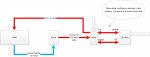
So here we go...this is the first picture as I understand it (see attached).

  1. Hydraulic fluid sits in the tank.
  2. The fluid is suctioned to the pump.
  3. The pump pushes the fluid to the 3 Pt Hitch valve under pressure.
  4. The valve passes fluid under pressure to the 3 Pt Hitch.
  5. Excess fluid returns to the tank.

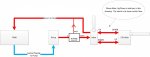
OK...let's see how close i got, and then we can move on.

Thanks,
Jim
 

Attachments

85Hokie

Moderator
Staff member
Lifetime Member

Equipment
BX-25D ,PTB. Under Armor, '90&'92-B7100HST's, '06 BX1850 FEL
Jul 13, 2013
10,395
2,199
113
Bedford - VA
Jim,

what you are "thinking" is correct - that high pressure is then diverted to where needed, fluid always flows!!!! NO matter what, there will be fluid flowing.

If you look at the hydraulics of a log splitter, it is simple but basically is what you described - the complications come in as the pathway is changed multiple times and branches off.

What thought, or end result are you looking to do?
 

ShaunBlake

New member
Lifetime Member

Equipment
B6100D; B219; Piranha bar; Hodge stabilizers; Filled Ag rears; R322T w/48" deck
Dec 21, 2014
899
1
0
81
Sugar Hill -- next door to Buford, GA
Jim, your schematic needs an important adjustment: the flow from the control to the 3PH must be bi-directional; fluid must be released else the 3PH won't lower. On a side note, it might be misleading to cross the arrows; I envision a circular path although I imagine you are suggesting an either-or condition.

BTW, I am a retired software engineer, so I can fully appreciate your quandary. Hydraulic diagrams and schematics make me crazy! (That's my excuse, and I'm stickin' to it!)
 

Kennyd4110

Well-known member
Vendor Member
Sep 7, 2013
1,174
341
83
Westminster, MD
www.boltonhooks.com
I am short on time, but I will add this for you to ponder, in a OC (Open Center) system, there is not real "pressure" built up until the fluid meets resistance, like trying to extend a cylinder-then the pressure will gradually rise as resistance increases until finally the PRV (pressure relief valve) opens to protect the system components.

When all valves are in neutral, there may be about 500psi of pressure in the system due to parasitic resistance through fittings and such.
 

CaveCreekRay

Well-known member
Lifetime Member

Equipment
L3800 HST, KingKutter box scraper, KingKutter 66" rake, County Pride Subsoiler
Jul 11, 2014
2,631
93
48
Cave Creek, AZ

jfnewell1965

New member

Equipment
B6200D
Aug 19, 2014
71
0
0
Katy, TX
www.jfnewell.com
All,

To answers questions that have come up::

85Hokie
The intent is to wind up with a working 3pt Hitch, a working hydraulic top link, and to eventually have the front connections power a FEL.

ShaunBlake
I think my second picture corrects the flow as you discussed.

Kennyd4110
I assumed the controls/valve/spool? I would be buying would be open center to keep the circular flow going.

CaveCreekRay
Wow...that piston is much larger than I imagine it would be. What model is that?
 

Kennyd4110

Well-known member
Vendor Member
Sep 7, 2013
1,174
341
83
Westminster, MD
www.boltonhooks.com

Attachments

Last edited:

CaveCreekRay

Well-known member
Lifetime Member

Equipment
L3800 HST, KingKutter box scraper, KingKutter 66" rake, County Pride Subsoiler
Jul 11, 2014
2,631
93
48
Cave Creek, AZ
Jim,

L3800. I bet yours is about the same size. The FORD in service that day had one half again as big.

Ray

Oh yeah... The "tank" in your drawing (on my machine at least) is the whole rear end aft of the tranny. Its just a big slosh chest for the gears. The 3pt bypass valve dumps the unported pressure back on top of the gear train keeping everybody slippery and happy.
 
Last edited:

cabu

New member
Lifetime Member

Equipment
Kuno B1-15 (B1502DT)
May 24, 2009
736
2
0
Germany, Oyten
Hello,

I have already added a 3way valve to my B1502.

I have a question to the drawing. Isn't it that the 3ph cylinder is only a single action one? So there is only one pipe going from the valve to the cylinder? The lifting is done by hydraulic and the gravity is lowering it, the speed depends on a flow adjustment valve (normally under the seat).
 

Kennyd4110

Well-known member
Vendor Member
Sep 7, 2013
1,174
341
83
Westminster, MD
www.boltonhooks.com
Hello,

I have already added a 3way valve to my B1502.

I have a question to the drawing. Isn't it that the 3ph cylinder is only a single action one? So there is only one pipe going from the valve to the cylinder? The lifting is done by hydraulic and the gravity is lowering it, the speed depends on a flow adjustment valve (normally under the seat).
Yes, you are correct.