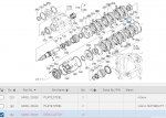
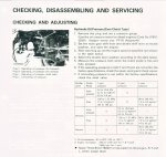
M6800 hydraulic shuttle

Fedup

Active member
Apr 6, 2016
207
58
28
Winchester
I'm trying to find some information on this shuttle system. I'm currently looking through a PDF of a WSM labeled M6800s. It has M6800 and M6800s but I can't seem to find anything relating to the hydraulic shuttle in there. Been going through it almost page by page and still haven't found anything helpful.

Maybe there's a newer book that covers this transmission option? I think there is a date code on this one that says issued 03 2008. Maybe this book is just too old?
 

Captain13

Active member

Equipment
M7040 4WD ROPS, ZD28, Woods (84” box blade, 72” harrow, 48” pallet forks)
Feb 27, 2019
516
168
43
Kathleen, GA
My 7040 probably has the same shuttle. In my WSM the hydraulic shuttle is covered in Section 3 which is the Transmission section. It cover synchro, hydraulic shuffle and shuttle shift. My WSM is for the 5040, 6040 and 7040.

Keep flipping through the sections till you see Transmission at the top of the page. Not a page at the time though. It’s about half way through in my WSM.
 

rbargeron

Well-known member
Lifetime Member

Equipment
L5450, L48, L3250, L345 never enough attachments
Jul 6, 2015
1,151
220
63
western ma
If I'm reading the parts diagrams right, the M6800H and M6800HDC models have a gear-type shuttle operated by hydraulic valves. Look for a manual that's for those H models. The shuttle is geared, although the pto has a hydraulic clutch.
What issues are you having? Dick B
 
Last edited:

North Idaho Wolfman

Moderator
Staff member
Lifetime Member

Equipment
L3450DT-GST, Woods FEL, B7100 HSD, FEL, 60" SB, 743 Bobcat with V2203, and more
Jun 9, 2013
28,929
5,288
113
Sandpoint, ID

Fedup

Active member
Apr 6, 2016
207
58
28
Winchester
Look on the last page of the manual you have.
Bet it says 9Y011-18008
You need 9Y021-18008
And no there is not a free or cheap version of this manual available out there.
Actually, I don't see either number listed anywhere on this PDF. Your statements pretty much match my own conclusion that this version of the manual simply doesn't contain a section (or portions of sections) on the hydraulic shuttle transmission. I guess I need to look elsewhere for anything on this system

I haven't yet mastered the new Kubota parts website, and there too, I'm finding very little to work with so far. If I'm getting this right it seems the shuttle is supplied through a single mechanical (not solenoid/electronic) valve, located on top of the clutch housing. This valve serves for both the fwd/rev direction clutch packs and the clutch pedal/inching functions. All mechanical. That's a switch in today's world.

I didn't find any breakdown on the valve itself that might help explain how any of that works. I did see a couple plugs listed that might be clutch pack test ports? Not sure, as they aren't labeled as such in the text.

I'm trying to diagnose a possible clutch slipping problem with the fwd direction pack, and not sure where to start. Parts list shows the transmission drives from a spring center drive plate on the flywheel, so that's not likely to be an issue. That leaves the clutch plates or the system pressure the way I see it. Possibly linkage related somewhere on the outside? I'd like to learn a little more about how the system works before making a trip out there.
 

TheOldHokie

Well-known member
Lifetime Member

Equipment
L3901/LA525, B7200DT/B1630, G2160/RCK60, G2460/RCK60
Apr 6, 2021
7,125
3,485
113
Myersville, MD
windyridgefarm.us
Actually, I don't see either number listed anywhere on this PDF. Your statements pretty much match my own conclusion that this version of the manual simply doesn't contain a section (or portions of sections) on the hydraulic shuttle transmission. I guess I need to look elsewhere for anything on this system

I haven't yet mastered the new Kubota parts website, and there too, I'm finding very little to work with so far. If I'm getting this right it seems the shuttle is supplied through a single mechanical (not solenoid/electronic) valve, located on top of the clutch housing. This valve serves for both the fwd/rev direction clutch packs and the clutch pedal/inching functions. All mechanical. That's a switch in today's world.

I didn't find any breakdown on the valve itself that might help explain how any of that works. I did see a couple plugs listed that might be clutch pack test ports? Not sure, as they aren't labeled as such in the text.

I'm trying to diagnose a possible clutch slipping problem with the fwd direction pack, and not sure where to start. Parts list shows the transmission drives from a spring center drive plate on the flywheel, so that's not likely to be an issue. That leaves the clutch plates or the system pressure the way I see it. Possibly linkage related somewhere on the outside? I'd like to learn a little more about how the system works before making a trip out there.
I know absolutely nothing about this machine but $98 for the Kubota workshop manual seems like an inexpensive source for the information you want.

Dan
 
  • Like
Reactions: 1 user

Fedup

Active member
Apr 6, 2016
207
58
28
Winchester
I know absolutely nothing about this machine but $98 for the Kubota workshop manual seems like an inexpensive source for the information you want.

Dan
Maybe so, but this is the first of these anyone has called me about, and chances are I may never see another one. I already have enough books on the shelf that I bought for "one time use" projects. If it needs to come apart, that's one thing. Right now I'm just trying to figure out how it works.
 

rbargeron

Well-known member
Lifetime Member

Equipment
L5450, L48, L3250, L345 never enough attachments
Jul 6, 2015
1,151
220
63
western ma
The clutch pack is generally a larger version of the one used for the Ever Clutch first used on L3 models. The Kubota parts website shows 2 versions - see below.

If it's slipping in one direction, not both, then it could be worn discs and steels.

I found the new Kubota Parts Lists a bit notchy at first - but they are actually quite good once you get navigating around by trial and error. I found that selecting model first brings up all the variants - select one with the H, then transmission, etc. -

M6800HD clutch transmission.jpg

M6800 H shuttle clutch pack (old type).jpg
 
Last edited:

North Idaho Wolfman

Moderator
Staff member
Lifetime Member

Equipment
L3450DT-GST, Woods FEL, B7100 HSD, FEL, 60" SB, 743 Bobcat with V2203, and more
Jun 9, 2013
28,929
5,288
113
Sandpoint, ID
The shuttle valve does 2 operations, clutch control and directional control.
Without the manual I don't know how exactly to tests the valve.
I suspect that the 2 ports would be pressure to the forward and reverse clutches.
I would also check the supply input.
Again without the manual I couldn't tell you what pressure they are supposed to be at.
The pressure relief valve could be than issue if the pressure is too low for the valves and clutch packs to operate effectively.
It could be effecting (or feel like it's effecting) forward more than reverse because of the lower gear ratio of reverse.
 

Fedup

Active member
Apr 6, 2016
207
58
28
Winchester
My 7040 probably has the same shuttle. In my WSM the hydraulic shuttle is covered in Section 3 which is the Transmission section. It cover synchro, hydraulic shuffle and shuttle shift. My WSM is for the 5040, 6040 and 7040.

Keep flipping through the sections till you see Transmission at the top of the page. Not a page at the time though. It’s about half way through in my WSM.
The shuttle valve on the 7040 is on the side of the clutch housing, not on top. Totally different valve body. Parts list shows the same two plug part numbers on both valves, possibly test ports? Does your manual show these as test ports? If they are what I think they are they will be 1/8" BSP allen head plugs.
 
Last edited:

Fedup

Active member
Apr 6, 2016
207
58
28
Winchester
The clutch pack is generally a larger version of the one used for the Ever Clutch first used on L3 models. The Kubota parts website shows 2 versions - see below.

If it's slipping in one direction, not both, then it could be worn discs and steels.

I found the new Kubota Parts Lists a bit notchy at first - but they are actually quite good once you get navigating around by trial and error. I found that selecting model first brings up all the variants - select one with the H, then transmission, etc. -

View attachment 75557
I agree completely. Worn plates is the first thought, but until I see it first hand, and check the pressures I can't make that call.

This is my first try at the new parts website, it caught me by surprise. I liked what they had before once I got used to it. I hope this really is "new and improved". Time will tell.
 

rbargeron

Well-known member
Lifetime Member

Equipment
L5450, L48, L3250, L345 never enough attachments
Jul 6, 2015
1,151
220
63
western ma
I agree completely. Worn plates is the first thought, but until I see it first hand, and check the pressures I can't make that call.

This is my first try at the new parts website, it caught me by surprise. I liked what they had before once I got used to it. I hope this really is "new and improved". Time will tell.
Yeah, and its a nasty surprise when you first need a quick lookup and hit the wall....I added another screen shot above in post #8 - notice the left pane is a pull-out from the side - if you don't guess that it stares at you like you're stupid (not far off in my case) - but after some thrashing I can at least do the basics - until they change it again o_O .

Found an $80 manual here
 
Last edited:

Fedup

Active member
Apr 6, 2016
207
58
28
Winchester
I haven't seen the tractor yet. In the absence of the "proper" manual, what I find so far is this. The shuttle valve is supplied with fluid from a tee placed in the return line from the steering controller to the pto valve. The pto valve has a built in relief valve which also serves as a system pressure regulating valve? This pressure is maintained at 355 to 370 psi. This seems to be a standard pressure for clutch packs on many other (if not all?) Kubota models. I can't help but think this tractor will follow suit and shuttle pressures should be just that.

If I check pressures at those ports, the findings are consistent with that, the slippage is still there, then the shuttle is going to have to come out. If that's the case, I guess I'll spring for the manual.
 

North Idaho Wolfman

Moderator
Staff member
Lifetime Member

Equipment
L3450DT-GST, Woods FEL, B7100 HSD, FEL, 60" SB, 743 Bobcat with V2203, and more
Jun 9, 2013
28,929
5,288
113
Sandpoint, ID
The pto valve has a built in relief valve which also serves as a system pressure regulating valve?
No, There is a separate line and PVR into the sump, it's not part of the PTO control.

M6800HD PRV.JPG
 

rbargeron

Well-known member
Lifetime Member

Equipment
L5450, L48, L3250, L345 never enough attachments
Jul 6, 2015
1,151
220
63
western ma
The WSM for my L5450 says with pedal up, "Ever Clutch" hydraulic pressure should be between 156 and 199 psi w/engine at 900 - 2600 rpm, all shifters in neutral.

The similar M6800H clutch packs have 12 plates instead of 10 - but I'm guessing operating pressure may be similar.

L5450 clutch pressure.jpg
 
Last edited:

Fedup

Active member
Apr 6, 2016
207
58
28
Winchester
No, There is a separate line and PVR into the sump, it's not part of the PTO control.

View attachment 75641
I saw that diagram as well, but there is no shuttle valve or PTO valve in it. There is another diagram right next to it that shows both valves and a similar tee in one of the oil cooler lines. This is going by parts page J27501. The pdf I'm studying leads me to believe the relief is IN the PTO valve, not a separate item. The breakdown of the PTO valve shows a relief valve and associated components in it, along with what must be an accumulator built into the manifold they refer to as the PTO clutch holder.

I guess I'll know more when I see the tractor.
 

North Idaho Wolfman

Moderator
Staff member
Lifetime Member

Equipment
L3450DT-GST, Woods FEL, B7100 HSD, FEL, 60" SB, 743 Bobcat with V2203, and more
Jun 9, 2013
28,929
5,288
113
Sandpoint, ID
I saw that diagram as well, but there is no shuttle valve or PTO valve in it. There is another diagram right next to it that shows both valves and a similar tee in one of the oil cooler lines. This is going by parts page J27501. The pdf I'm studying leads me to believe the relief is IN the PTO valve, not a separate item. The breakdown of the PTO valve shows a relief valve and associated components in it, along with what must be an accumulator built into the manifold they refer to as the PTO clutch holder.

I guess I'll know more when I see the tractor.
Yea I see where you are getting confused:

The 2 different pages are an extension of each other with grey area's overlapped.
It's all the same circuit.
The noted yellow on both prints is the tee to the PRV.
M6800HD J27001B.JPG

M6800HD J27501B.JPG
 

Attachments

Fedup

Active member
Apr 6, 2016
207
58
28
Winchester
You're right, that does confuse me. I do see the point that it's all one circuit diagram in two separate overlapping forms. I also see both tees are on the same circuit. It's the return line from the steering valve. Difference is the one you mentioned is ahead of the oil cooler, the other is behind it. Makes me think there are two valves, one just to limit the pressure through the cooler, and one to limit the pressure through the PTO, (and maybe the shuttle valve as well).

Too bad there is no breakdown on the shuttle valve.
 

whitetiger

Moderator
Staff member

Equipment
Kubota tech..BX2370, RCK60, B7100HST, RTV900 w plow, Ford 1100 FWA
Nov 20, 2011
2,614
1,132
113
Kansas City, KS
You're right, that does confuse me. I do see the point that it's all one circuit diagram in two separate overlapping forms. I also see both tees are on the same circuit. It's the return line from the steering valve. Difference is the one you mentioned is ahead of the oil cooler, the other is behind it. Makes me think there are two valves, one just to limit the pressure through the cooler, and one to limit the pressure through the PTO, (and maybe the shuttle valve as well).

Too bad there is no breakdown on the shuttle valve.
Will this help you out any?
 

Attachments

  • Like
Reactions: 1 user

Fedup

Active member
Apr 6, 2016
207
58
28
Winchester
Will this help you out any?
It certainly does. That shows the system pressure to be 355 -370 psi, pretty much as I expected from research so far. The surprise is finding that the valve dumbs that down to 250 or so to the clutches themselves. Seeing that on the gauges would have sent me looking for internal leaks which may not even be there.

Another surprise is the location of the valve. On open station tractors it's under the steering column and on cab machines it's under the seat? Not sure how to process that. Maybe that's covering different models?