Having multiple new relays be faulty is very unlikely.
Let's verify a few things as you've done a great deal of testing and it needs to be in one location to make it easier to follow.
First off there are two circuits needed for the glow plugs to function. 1) The low side or control circuit is used to energize the magnetic coil inside the relay to throw the contacts for the High side circuit. The low side is controlled by the CPU which takes into account coolant temperature to adjust the GP on-time. 2) High side or the main power supply to the Glow Plugs. The high side gets it's power directly from the battery after passing through the 50 amp slow burn fuse. This wire goes to the relay socket directly.
Let's first verify the high side circuit is functioning correctly.
Remove the wire at the GP buss bar.
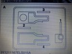
Remove the Relay and jump the terminals with the black/red tracer (terminals 1 and 2).
Do you have battery voltage at the buss bar wire? Yes and this circuit is OK.
Low side.
Verify you have battery voltage at the Terminal 3 of the relay socket when the key is ON. (Meter: positive or red wire to terminal 3 and black wire to ground)
Do you have battery voltage?
Please confirm the results, even if you have to retest a few things.
Here to support.
Let's verify a few things as you've done a great deal of testing and it needs to be in one location to make it easier to follow.
First off there are two circuits needed for the glow plugs to function. 1) The low side or control circuit is used to energize the magnetic coil inside the relay to throw the contacts for the High side circuit. The low side is controlled by the CPU which takes into account coolant temperature to adjust the GP on-time. 2) High side or the main power supply to the Glow Plugs. The high side gets it's power directly from the battery after passing through the 50 amp slow burn fuse. This wire goes to the relay socket directly.
Let's first verify the high side circuit is functioning correctly.
Remove the wire at the GP buss bar.
Remove the Relay and jump the terminals with the black/red tracer (terminals 1 and 2).
Do you have battery voltage at the buss bar wire? Yes and this circuit is OK.
Low side.
Verify you have battery voltage at the Terminal 3 of the relay socket when the key is ON. (Meter: positive or red wire to terminal 3 and black wire to ground)
Do you have battery voltage?
Please confirm the results, even if you have to retest a few things.
Here to support.
Attachments
-
 91 KB Views: 123
Last edited:
