I am pretty analytical myself

and I have spent some time learning about gears. I understand the geometry of the involute tooth design and why it is used but its not as simple as you think. Here is a brief excerpt from a technical article describing the meshing action of plain spur gears.
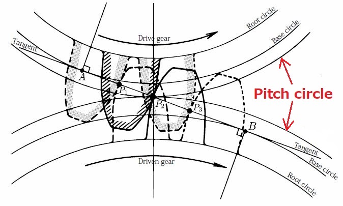
When gear teeth mesh, they roll and slide together.
The first point of contact is near the root of the driving tooth and the tip of the driven tooth. As contact between the gear teeth progresses, sliding predominates while rolling is minimized. However, the opposite occurs when mid point tooth contact is reached, and sliding is reduced as rolling predominates. At the pitch line, sliding is zero and rolling is maximized.
As the gears come out of the mesh, sliding progresses
That was authored by Mobil as part of an extended technical analysis of the performance requirements for gear oils.
So even plain involute spur gears slide against one another. That sliding action becomes more pronounced in a plain spiral bevel gear set where there is more overlap of tooth mesh. Hypoid spiral bevel gears produce even more tooth overlap and even more sliding. Worm gears are worse yet. All of those designs are used with the expectation the gears will "last".
And as I said earlier that's why spiral bevel gears require a lubricant with elevated levels of extreme pressure additives (API GL4). Hypoid spiral bevel gears require even higher EP treat rates (API GL5).
Dan