Hello to all..
I am brand new to the forum and have a question.
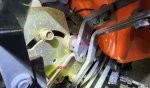
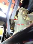
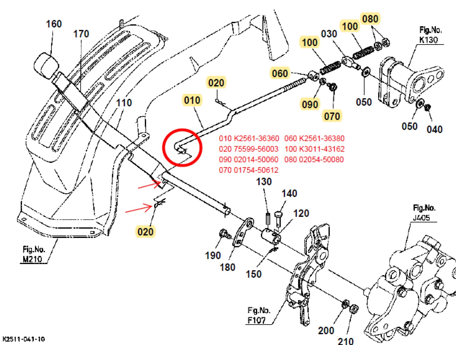
My 2005 BX1500D has approximately 510 hours and the feed back rod (010) that returns the hydraulics lever for the 3 point hitch to the neutral position has been broken for years. No rhyme or reason as to why, just broke clean sometime after the first few years. Since it broke I have been manually returning it as I use it, so I haven't really had any performance issues. As best as I can determine it serves no other purpose than to return the lever for you and stop the up/down pressure to the hitch. It would be nice, though, to have it functional and to perform as it was designed.
With that in mind, I did some investigation and even got a quote from the dealer. To replace the broken rod = $715, $105 is parts (highlighted below) and $615 labor plus $70 tax coming to a grand total of $785. Like I said it works fine as it is.
Seems you have to disassemble the tractor to get at the rod to remove it. Back when I worked on jets and heavy duty diesels we used to say they started with the engine (drive train) and then built the truck/plane around it. Still, I would like for it to work, so I thought I would see if anyone has experience in this area and maybe has a trick or alternate method of making this repair. At the very least some steps as to what would have to be removed at a minimum to facilitate replacement.
I can see the end where it attaches and can remove retaining clip/pin (020), identified by the red arrows below, but there is not enough clearance to slide rod left (inboard) out of the bracket. In the image below the retaining clip is on the inboard side of the bracket and it appears as though the rod could be easily removed, however in real life it is on the outboard side and, as I mentioned, not enough clearance to remove it.
Any feedback (pun intended) you may be able to provide is greatly appreciated.
I am brand new to the forum and have a question.
My 2005 BX1500D has approximately 510 hours and the feed back rod (010) that returns the hydraulics lever for the 3 point hitch to the neutral position has been broken for years. No rhyme or reason as to why, just broke clean sometime after the first few years. Since it broke I have been manually returning it as I use it, so I haven't really had any performance issues. As best as I can determine it serves no other purpose than to return the lever for you and stop the up/down pressure to the hitch. It would be nice, though, to have it functional and to perform as it was designed.
With that in mind, I did some investigation and even got a quote from the dealer. To replace the broken rod = $715, $105 is parts (highlighted below) and $615 labor plus $70 tax coming to a grand total of $785. Like I said it works fine as it is.
Seems you have to disassemble the tractor to get at the rod to remove it. Back when I worked on jets and heavy duty diesels we used to say they started with the engine (drive train) and then built the truck/plane around it. Still, I would like for it to work, so I thought I would see if anyone has experience in this area and maybe has a trick or alternate method of making this repair. At the very least some steps as to what would have to be removed at a minimum to facilitate replacement.
I can see the end where it attaches and can remove retaining clip/pin (020), identified by the red arrows below, but there is not enough clearance to slide rod left (inboard) out of the bracket. In the image below the retaining clip is on the inboard side of the bracket and it appears as though the rod could be easily removed, however in real life it is on the outboard side and, as I mentioned, not enough clearance to remove it.
Any feedback (pun intended) you may be able to provide is greatly appreciated.