I recently just finished restoring an old Kubota B20 TBL and am loving it! One pesky problem I haven't been able to solve though is height control lever for the 3 point hitch.
This one has the control style where you set the lever for a certain position, and the implement moves to that position. As you then move the lever up and down anywhere in its range, the 3ph follows, as opposed to the style where the lever has an up / neutral / down position and the neutral holds whatever the current position.
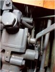
The problem with mine is the lever will not stay where you put it. It feels spring loaded, wanting to always immediately return to the full down position.
The previous owner had tied a string to it with several knots to hold the lever where he wanted it. So far I have been using a dirt bike handle bar-end with a piece of rubber hose jammed into the lever slot to act as a physical position stop. Its a hassle to adjust when working with implements that have lots of up / down operations, and sometimes bounces loose dropping the implement down when the tractor gets bouncy.
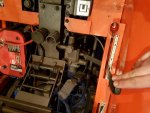
I have found some other threads with different models talking about the same issue where they said the fix was to tighten a couple of nuts on the lever shaft to increase the friction / tension. That does not seem to help for mine. I have already tried tightening the 13mm nut as tight as I am comfortable tightening it, and no change on the tension / friction when moving the lever.
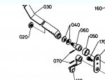
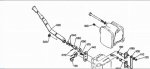
The parts diagram shows that that the lever (30) is attached to the shaft (60) with a machined flat. The nut (20) just holds the lever onto the flat and the lever / nut / shaft all move as one piece. The shaft (60) is in turn attached to the internal valve with a roll pin (70).
Does anybody have any experience with these or ideas to try?
This one has the control style where you set the lever for a certain position, and the implement moves to that position. As you then move the lever up and down anywhere in its range, the 3ph follows, as opposed to the style where the lever has an up / neutral / down position and the neutral holds whatever the current position.
The problem with mine is the lever will not stay where you put it. It feels spring loaded, wanting to always immediately return to the full down position.
The previous owner had tied a string to it with several knots to hold the lever where he wanted it. So far I have been using a dirt bike handle bar-end with a piece of rubber hose jammed into the lever slot to act as a physical position stop. Its a hassle to adjust when working with implements that have lots of up / down operations, and sometimes bounces loose dropping the implement down when the tractor gets bouncy.
I have found some other threads with different models talking about the same issue where they said the fix was to tighten a couple of nuts on the lever shaft to increase the friction / tension. That does not seem to help for mine. I have already tried tightening the 13mm nut as tight as I am comfortable tightening it, and no change on the tension / friction when moving the lever.
The parts diagram shows that that the lever (30) is attached to the shaft (60) with a machined flat. The nut (20) just holds the lever onto the flat and the lever / nut / shaft all move as one piece. The shaft (60) is in turn attached to the internal valve with a roll pin (70).
Does anybody have any experience with these or ideas to try?
Attachments
-
 19.9 KB Views: 1,963
 -
 91.7 KB Views: 1,878