I keep getting questions about finding a source of 12V power AND finding some switched power (power that goes off when the ignition is turned off) on the BX Series Tractors. I'm going to keep this short......for more info on this and other mods, you can go to my YouTube Channel (Http://BotaTrac.com). I will have some video's up by the end of the week. I'd appreciate it if you'd subscribe also!
Two problems exist:
1. No readily available source of 12V SWITCHED power
2. No room in the fuse box to add another circuit.
Being a conspiracy theorist at heart - I'm pretty sure Kubota does this intentionally.
SERIOUS NOTE: Also remember that cutting into your wire harness voids your warranty. Also, Use a test light just to double check your switched power circuit. Just because it worked like this on mine - well, please double check on yours before you cut into the harness if you decide to proceed.
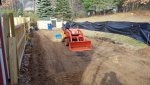
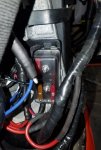
I took 3 30" pieces of 12ga wire and connected them directly to the positive side of the battery with inline fuses, ran them over the top of the battery box and cased them in corrugated loom. (See Pic 1)
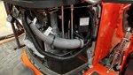
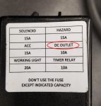
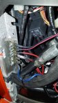
Located and removed the existing OEM Fuse box and located the fuse that powers the DC outlet (this one is switched by the ignition See Pics 2&3)
Spliced a 30" piece of 14ga wire into the load side of the DC outlet wire (which is also 14ga) - made sure to protect it with an inline fuse close to the fusebox. Remember, the new waterproof fusebox is going to supply 12V low amperage power to the low side of the relay's ONLY. DO NOT put any other devices into the new fusebox or you'll be calling for too much amperage through the ignition switch. That's what the 3 12ga wires that are connected to the battery terminal and fused inline are for.....getting more and expandable sources of 12v under the hood for accessories.
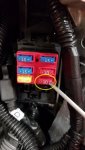
I then Installed the waterproof "add-on" fusebox and powered it with fused 14ga wire from the DC outlet splice. (Yes, the device will be double fused ultimately. See Pic4)
I Installed a Ground Buss Bar and grounded it to the battery's negative terminal and the frame (Yes, double grounded see Pic 5). This was purely for convenience.
I Wired the "low end" of the relay to the new waterproof fusebox on the line side and a switch to the load side.
Then, I wired two of the three 12ga power wires to the "high side" of the relay and then to the light fixture. ......done! The third could be used for future use.
Here's what's happening: The ignition is putting power to the switch through the waterproof fusebox when the key is now turned on. You can now turn your light switch on and your lights will illuminate. If you forget to turn off the rocker switch for the lights, they will now go off when the ignition is turned off.
Simply put: The ignition is powering the "low side" of the relay(s) and the battery is powering the "high side" of the relay(s).
Hope this helps - I know relay's can be complicated until you do a couple.
Two problems exist:
1. No readily available source of 12V SWITCHED power
2. No room in the fuse box to add another circuit.
Being a conspiracy theorist at heart - I'm pretty sure Kubota does this intentionally.
SERIOUS NOTE: Also remember that cutting into your wire harness voids your warranty. Also, Use a test light just to double check your switched power circuit. Just because it worked like this on mine - well, please double check on yours before you cut into the harness if you decide to proceed.
I took 3 30" pieces of 12ga wire and connected them directly to the positive side of the battery with inline fuses, ran them over the top of the battery box and cased them in corrugated loom. (See Pic 1)
Located and removed the existing OEM Fuse box and located the fuse that powers the DC outlet (this one is switched by the ignition See Pics 2&3)
Spliced a 30" piece of 14ga wire into the load side of the DC outlet wire (which is also 14ga) - made sure to protect it with an inline fuse close to the fusebox. Remember, the new waterproof fusebox is going to supply 12V low amperage power to the low side of the relay's ONLY. DO NOT put any other devices into the new fusebox or you'll be calling for too much amperage through the ignition switch. That's what the 3 12ga wires that are connected to the battery terminal and fused inline are for.....getting more and expandable sources of 12v under the hood for accessories.
I then Installed the waterproof "add-on" fusebox and powered it with fused 14ga wire from the DC outlet splice. (Yes, the device will be double fused ultimately. See Pic4)
I Installed a Ground Buss Bar and grounded it to the battery's negative terminal and the frame (Yes, double grounded see Pic 5). This was purely for convenience.
I Wired the "low end" of the relay to the new waterproof fusebox on the line side and a switch to the load side.
Then, I wired two of the three 12ga power wires to the "high side" of the relay and then to the light fixture. ......done! The third could be used for future use.
Here's what's happening: The ignition is putting power to the switch through the waterproof fusebox when the key is now turned on. You can now turn your light switch on and your lights will illuminate. If you forget to turn off the rocker switch for the lights, they will now go off when the ignition is turned off.
Simply put: The ignition is powering the "low side" of the relay(s) and the battery is powering the "high side" of the relay(s).
Hope this helps - I know relay's can be complicated until you do a couple.
Attachments
-
 65.9 KB Views: 665
 -
 71.1 KB Views: 685
 -
 45.9 KB Views: 669
 -
 58.5 KB Views: 658
 -
 70 KB Views: 657
Last edited: