Kubota 3rd Function Kit Install (Lxx60 HSTC) part# L2265

fishpick

Active member

Equipment
BX24 & L4760HSTC
Dec 16, 2017
112
192
43
The High Taxes part of lovely NY, USA
I’m gonna chronicle in this post the installation of the Kubota OEM 3rd function on an L4760 HSTC tractor.
The printed instructions are in the Loader Assembly Instructions manual for a LA555/LA855/LA1055 loader - they do NOT come with the kit. Ask your dealer for the above document - the steps are in there. This is on a LA1055 - but it's almost the same, only real difference is the smaller loaders have 2 orange shims that come in the kit that go behind the solenoid.
There are basically 4 general groups of steps :
  1. Mount the guard and solenoid and piping
  2. Run the lines up the loader and mount the connector block on the loader
  3. Splice in the hydro lines and connect to the solenoid
  4. Swap the joystick and connect the new
So far I have completed the first 2 easy groups of steps. The first 2 groups of steps can be done and then if you need to you can still use the tractor. Groups 3 and 4 "break" the tractor while you are doing them.

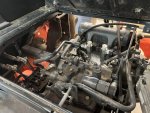
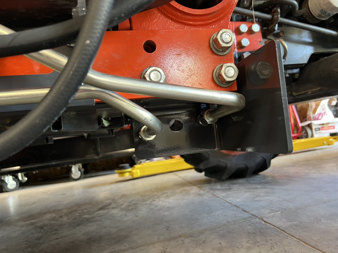
Here’s the guard mounted on the loader frame. It mounts behind it and will have the hard lines for the hydro connect through it. You can see the lines already in this pic. Those capped ends will attach to the power beyond and return lines that you plumb in later in group 3 steps.
EF918243-F244-4FDA-80FA-D9858CACC881.jpeg

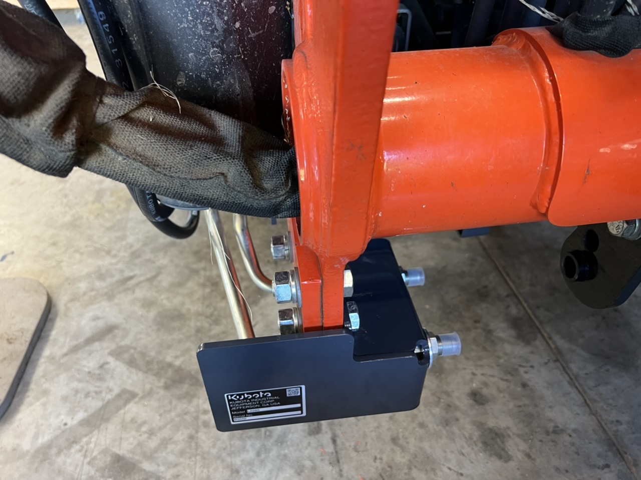
This is how the lines go through. The lines get installed after this plate and the solenoid get installed. The big washer goes on the back of the plate then the nut on the fitting (not seen)
F25A3FDB-1737-4942-B1CE-368E1AF7628C.jpeg

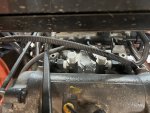
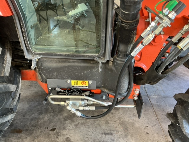
Here’s the solenoid. Note to install this - remove the step. Way easier since it's heavy and after you get it mounted you then have to mount the 2 hardlines shown in the above to pictures. Just a lot more room then. Also in this pic are the lines to the mounted connectors on the solenoid up to the QD block added to the loader behind the loader QD connections. The green and gray caps you see are the new ones. Also note here - the gray cap uses the gray hose to the rear most connection. That's in the instructions but this is apparently a place people mess up.
CCAB4EFE-D412-498A-A4A8-50F2D029E8EE.jpeg

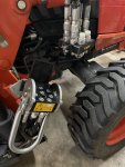
Here’s those lines entering an opening in the loader you have to open - there are 4 10mm bolts holding this plate on and an identical one at the bottom of the boom on the inside. You feed the 2 hoses down through the boom here and it's a little effort t opull the bend fitting out the bottom... you actaully stuff less hose in than you think and I found it suddenly very easy to pull them out the bottom when I adjsted how much was inside the boom so just the tips were able to be grabbed.
7F7F299A-6E48-4E2D-AB9F-4970A79EF9AB.jpeg

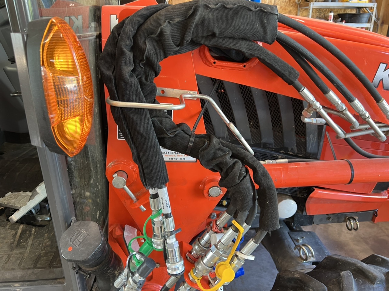
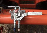
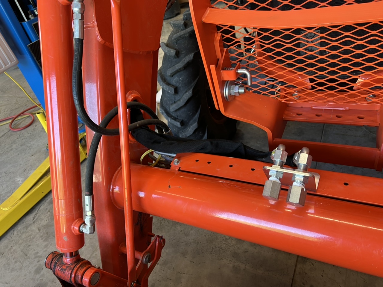
Here's the hoses coming out on the bottom front of the boom. And here’s the connector block on the front. To mount this I had to remove the guard plate it’s bolted to In order to get my bolts in. You will note - the 2 ends are DEAD HEADED... You must supply your own connectors. I'll be installing those at the end.
B911B56D-6763-4BCB-9557-A03C32F4732F.jpeg
 
Last edited:
  • Like
Reactions: 5 users

fishpick

Active member

Equipment
BX24 & L4760HSTC
Dec 16, 2017
112
192
43
The High Taxes part of lovely NY, USA
Group of Steps 3 "Splice in the hydro lines and connect to the solenoid".
This was expected to be the hardest part of the process - and it did not disappoint. This series of steps is not fun!

This starts with unbolting the seat and tilting it back - there's even a prop rod built in to hold it open.
IMG_2467 Large.jpeg

Once you get this far - the fun ends... see that hexagonigal 24mm wrench tube looking thing in there with the 27mm fittings on the end... That's it after sitting for 8 hours with some real good penetrating oil on the fittings.
IMG_2468 Large.jpeg

You will need a long 27mm wrench - even better I think would be a 27mm and 24mm crows foot wrench end and 2 long breaker bars... Because those fittings are TIGHT... You will be swearing sweating and stuck here for a bit... but keep at it - and the tube will come off. You will note in this picture I still have the holders for the hard lines connected - that seemed was safer as I was reefing on things to prevent screwing up a hardline. Ultimately I ened up disconnecting the ground wire (it's off in the pic) and the 2 return breather lines from the rear cylinders. That gives you a little more room to work.
IMG_2469 Large.jpeg

When you get that off - you will then install the 2 90* elbows that replace the tube... and then clean up a LOT of leaked fluid. Note the ground is still disconnected and 1 of the breathers is disconnected. Also - for folks who freak out about Teflon tape - you don't use it for tapered fittings... but these do not have a taper (unlke the top you see under the cover) and I was told these should get tape. And given how freaking hard it is to re-tighten these - I think I understand why I was told to either tape or dope em. Getting these to NOT rotate when you get tight is a joy.
IMG_2475 Large.jpeg

One huge tip - think 3 dimensional - I found I could clean up the fluid, manipulate the hardlines and even in some cases hold things or brace them to tighten the big fittings better from the back of the tractor.
IMG_2473 Large.jpeg

Once you get those 2 fittings done - the rest is a cake walk - the instructions do have a diagram that is rotated 90* so when you are looking at it - the routing of the lines does not make sense until you realize that... then - it's a matter of pulling the 2 new hoses down to the hardline input and return on the mounted solenoid. The instructions on routing are fairly vague - so I took my time and ran these hoses up inside of other hardlines and around the filters to prevent them from being easily snagged. NOTE - the hose with the green paint or tape goes on the fitting you see it on - and the same goes for up front. It matters!
IMG_2476 Large.jpeg

After the lines are run - you connect them following the color coding in the instructions to the hardlines. In my case this was a little more difficult because I have to make sure the lines give me room for the front mounted snow blower pins as well. You can see the pin hole between the hoses - and I tested the pin as well. In this picture they fitting are not tightened yet.
IMG_2477 Large.jpeg

That last picture is my only real complaint with the kit so far... it really would have been nice if Kubota had that gray metal plate there from the very first step have an extended portion in towards the tractor some to protect these hoses. I'm not overly worried about things grabbing hoses and breaking them - but man - that's pretty exposed right there... eventually I think I might weld a guard in place here that I can ensure still won't interfere with the blower.

That's it - the next step is group 4 - electrical. And that shouldn't be too bad I hope.
 

Attachments

  • Like
Reactions: 3 users

kubotafreak

Well-known member

Equipment
GRAND l6060, L3560, B6100, gr2100, tg 1860, g1800, g1900, g2160
Sep 20, 2018
1,020
374
83
Arkansas, US
I did this to mine. Every little bit helps. (90-45)
1EB1C512-109A-4375-AE1E-ACC88DC54EE7.jpeg
 
  • Like
Reactions: 1 user

fishpick

Active member

Equipment
BX24 & L4760HSTC
Dec 16, 2017
112
192
43
The High Taxes part of lovely NY, USA
Group of Steps #4 Swap the joystick and connect the new one and buttons and stuff.
This is pretty simple stuff. The magic here over the "one size fits many" 3rd party kits is how simple all this works for switched power, the button to enable the solenoid, etc... Again - I have installed (cobbled) a lot of 3rd part "kits" on things with engines... and this OEM one really is excellent - and factory perfect.

This process starts inside the cab - where you have to pull off the old joystick topper and also remove the right side trim panel to get to the wiring. While I thought I took pics - I guess I didn't - but the instructions are clear on how to remove the joystick head and the trim. The instructions are also clear on what to cut out of the rubber boot and how much to shorten the cover on the joystick.
The next part is the wiring harness - and the only thing that does not connect clearly is the power that makes the whole thing work. There's an unmated connector in the back of your cab on the left side - that is what goes into the green female connector on the harness. Here it is plugged in.
IMG_2480 Large.jpeg

Next you will feed the harness wit hthe 4 plugs that go to the solenoid out through the rubber plug in the back of the cab. This picture is the left back corner of the cab behind the seat. Yo ucan see the hole where the rubber plug goes and the wiring harness going out that hole.
IMG_2481 Large.jpeg

Here it is from the back of the tractor outside with the pug cut per the instructions and the correct routing behind the blinker wire.
IMG_2482 Large.jpeg

I "sorta" followed the routing instructions for the wiring harness from the back to the solenoid - but I think I found a better path that's even more out of the way of the wheel and anything it might spin up. For example - this is one of the places they wanted you to attach the harness to - and I didn't like anything in the wheel well.
IMG_2486 Large.jpeg

I did find a nice open hole up under the cab to zip tie the harness to - you can see it in this picture above and to the right of the 2 connector nuts - keeps it way up nice and high and away from everything else.
IMG_2485 Large.jpeg

When you get it to the solenoid - I came down between the frame and the loader frame here right by the gas tank and then up into the solenoid space - the only connection that really matters is the solenoid plug on the FRONT goes to the harness with the red and black wires.
IMG_2483 Large.jpeg

This picture here is how NOT to run things- this was to test the electronics before I routed things where I wanted them - you should not have anything dangling or hanging!
IMG_2484 Large.jpeg

But that's it - once you get the harness routed and safely secured away from moving parts and wheels... and all the wires tucked up into the solenoid / relay area with the plugs sheltered - you can put the cover on.... but I'd recommend you fully test the system to check for leaks and stuff before closing it all up.

One thing - I guess it's the only "defect" in the whole kit - is this... when I went to put the cover over the solenoid - it just would not fit... I kept looking and it turns out - very specific in the instructions when you are in step group 1 of installing the solenoid - the rear most connector should be angled downward slightly - look at the above pic - and you will see that. That was how it CAME. Except - also looking above - you can see the hose goes BELOW the bottom of the solenoid... I had to slightly loosen the factory position and "flatten" it out a bit so it didn't drop below the solenoid - then the cover fit just fine. This is how it SHOULD look. (the connection to the left NOT the wiring)
IMG_2487 Large.jpeg

I'll also admit a mistake... so - I was done - was excited to get the grapple on and try it... so - I hooked everything up - and started the tractor. I was smart to pull the tractor back into the barn incase something happened - it would be easier to fix there... I pressed the button on the joystick to activate the system - and it turned green (picture below shows the button and the joystick earlier in the process but for completeness) - anyhow, I put my thumb on the toggle - heard the solenoid engage - nothing... the sound of a bypass... tried the other direction... same thing...
IMG_2479 Large.jpeg

Then it hit me - go back to the first post in this thread - 4th picture... yeah - ya kinda gotta hook up those hoses too ;) Lucky for the - those lines were full of air - so even tho I had deadheaded the system - there wasn't so much pressure i couldn't get the fittings on (because air compresses!)... after that - things worked like a champ.

Anyhow - all in all I give the kit a solid 8.5 out of 10 - instructions were a little vague but totally able to figure them out so I deducted .5 points here... but they also aren't written for me - they are for the guys that put these together for a living... even so - I think they could be clearer. All the kit parts were top quality no complaints there. I think the biggest dissapointment is how the hoses come off the solenoid hardlines - that's a mess waiting to be ripped off even in moderate brush I think. If those lines were the lines to the 3rd function o nthe loader - I guess I wouldn't worry - one rips off - you day is done, drive back ot the barn... but they are not - they are the power beyond and return lines... It's kinda like having your aorta as a 6th finger - it's not if but when you are gonna pop it, slice it, snag it, slam it and die. That's a horrible design with no protection off the plate they supply. 100% I'll be adding some 90 degree elbots there to keep things tucked up more and less snag-able. I think even just that will be probably enough protection for all but the most "I drive through brush for fun" folks.
 
Last edited:
  • Like
Reactions: 5 users

fishpick

Active member

Equipment
BX24 & L4760HSTC
Dec 16, 2017
112
192
43
The High Taxes part of lovely NY, USA
Couple additional pics after things are wrapped up.
Here’s the side cover behind the reinstalled step.
50F857B1-97BB-4CCA-B9A3-FE950F8FA416.jpeg

And the bring your own connectors…(attached to the grapple that caused all this work) as you can see I didn’t go all flat faced fancy as they are about 3x more per connector and this isn’t a worksite tractor. No need for them in my opinion.
B09F7793-095C-40B5-B0CB-2E117B96B458.jpeg

And finally - the most important part of the kit. Affixed where the instructions say to affix. The white sticker to tell you how the system works…
C8DB230F-D2A7-4901-AFD6-D1EC35774BB4.jpeg
 
  • Like
  • Love
Reactions: 3 users

Popgadget

Member

Equipment
L6060
Mar 11, 2020
42
15
8
PA
I would heartily recommend this hydraulic quick connect for the 3rd function implements, it’s a Kubota option. There is also one available with 8 ports to connect the loader with the third function lines as well. I can dismount the LA1055 in under 2 minutes, and mount it in the same amount of time.
 

Attachments

  • Like
Reactions: 1 user

fishpick

Active member

Equipment
BX24 & L4760HSTC
Dec 16, 2017
112
192
43
The High Taxes part of lovely NY, USA
One last step - make sure you top off your hyro fluid (Super UDT 2) after the system is operational - there's a lot of new tubing and valves that will drop your levels low. I realized that when I did my pre-work dipstick checking before heading out the new grapple to move some serious logs!
 
  • Like
Reactions: 1 user

Batripp

New member

Equipment
L5460 ROPS
Jan 12, 2023
9
4
3
Shibleys Point Mo
There is so little info on the Grand series and this option. No place in the web can you see the install instructions and the one video I saw was pretty incomplete. Thanks!
 
  • Like
Reactions: 1 users

Batripp

New member

Equipment
L5460 ROPS
Jan 12, 2023
9
4
3
Shibleys Point Mo
Fishpick,
As I review the instructions and your post the only part that seems to lack info is the electrical connection part. Is it one of those things that easier once your looking at the tractor harness under the lever housing and L2265 harness? Are they color coded (besides the red/black) mentioned in the instructions?
Thanks in advance.
 

fishpick

Active member

Equipment
BX24 & L4760HSTC
Dec 16, 2017
112
192
43
The High Taxes part of lovely NY, USA
Fishpick,
As I review the instructions and your post the only part that seems to lack info is the electrical connection part. Is it one of those things that easier once your looking at the tractor harness under the lever housing and L2265 harness? Are they color coded (besides the red/black) mentioned in the instructions?
Thanks in advance.
The instructions are lacking in this area - and so is my writeup... because you can't mess it up. I think every single connector on the harness is different - and that makes it actually really easy to figure out when you get into the panel. You will see what goes where and then when you are done, if you are like me, say "damn - I wish all wiring was this stupid simple".

Only hard part - getting the harness to stay out of the way of any rear remote of other levers... but the Christmas tree pin on the harness fits into the bracket for the rear remotes (if you have any) and holds things out of the way there too!
 
  • Love
Reactions: 1 user

Batripp

New member

Equipment
L5460 ROPS
Jan 12, 2023
9
4
3
Shibleys Point Mo
The instructions are lacking in this area - and so is my writeup... because you can't mess it up. I think every single connector on the harness is different - and that makes it actually really easy to figure out when you get into the panel. You will see what goes where and then when you are done, if you are like me, say "damn - I wish all wiring was this stupid simple".

Only hard part - getting the harness to stay out of the way of any rear remote of other levers... but the Christmas tree pin on the harness fits into the bracket for the rear remotes (if you have any) and holds things out of the way there too!
 

The Evil Twin

Well-known member

Equipment
L2501, LA526,
Jul 19, 2022
2,382
2,292
113
Virginia
How much clearance to you have with the grapple rolled all the way back? I'm going to figure a way to mount my couplings parallel to the cross beam. Different equipment, but mine are pretty smooshed when I roll all the way back.
 

Batripp

New member

Equipment
L5460 ROPS
Jan 12, 2023
9
4
3
Shibleys Point Mo
That’s good news and helps justify the money for the OEM solution instead of the aftermarket.
Thanks again for your install pics and tips
 

Batripp

New member

Equipment
L5460 ROPS
Jan 12, 2023
9
4
3
Shibleys Point Mo
Installed the kit and it went pretty much without a hitch. My L5460 is a ROPS model so I think that made working on the electrical and plumbing in the Hydraulic much easier. Your post and picks made it much easier.
9ED9A448-1F4A-462D-90A6-27EACAB08155.jpeg
 
  • Like
Reactions: 1 user

mtdave

New member

Equipment
L4060HSTC
Jan 3, 2022
23
3
3
Michigan
This is a great write up, thank you. I have two questions, hopefully someone can answer:
1. Does anyone have a pdf of the loader assembly manuals where these instructions are printed? I've looked everywhere and can't find the manual.

2. Do the instructions, or anyone's experience, describe how to make the connections under the seat if the piping for the backhoe is installed? I already have the tee's shown that run to the backhoe. Would the new tee connect to the existing tee?
 

kubotafreak

Well-known member

Equipment
GRAND l6060, L3560, B6100, gr2100, tg 1860, g1800, g1900, g2160
Sep 20, 2018
1,020
374
83
Arkansas, US
This is a great write up, thank you. I have two questions, hopefully someone can answer:
1. Does anyone have a pdf of the loader assembly manuals where these instructions are printed? I've looked everywhere and can't find the manual.

2. Do the instructions, or anyone's experience, describe how to make the connections under the seat if the piping for the backhoe is installed? I already have the tee's shown that run to the backhoe. Would the new tee connect to the existing tee?
IMG_4949.jpeg

You may or may not have the gray tank hose depending on which kit you have