
1999 M120 Kubota 3pt lift lockout (2026 thread)

Pmschmitt

Member

Equipment
Rtv CPX1140, ZD28
Mar 17, 2019
43
1
8
Navasota, Texas
I purchased a used 2wd 99 M120 tractor at auction. The original auction listing mentioned nothing about the 3pt not operating. When I arrived the previous owner stated it was finicky.

Tractor runs and drives well, but the 3 pt light on the dash is rapidly flashing. I have downloaded the WSM and ran the internal diagnostic code shack for the 3 pt.

3pt codes

2-lift arm sensor
4-hydraulic control lever sensor
7-lift arm top limit adjuster
8-draft sensor
14-draft ratio adjustment dial
15-3 point hitch lowering speed adjustment

Error codes 7, 14,15 all originate from the right arm rest potentiometers(dials) when pinned out there is 5v entering and a good ground but no change in voltage on the signal wires leaving the controls when the knobs are turned.

I feel it would be odd for all 3 dials to be stuck at 0 if they are in fact fried.


Error code 8 draft control went away shortly when I was recycling and trying to clear codes but later returned. I have taken all the connections apart and cleaned them with cleaner and applied die electric grease.

error code 2 -lift arm sensor - I removed the sensor and checked the ohm resistance and it is appropriate. I checked the continuity of the wires for a short and they were clean. The code still remains

Error code 4- hydraulic control level sensor ( the lever that goes up and down for 3 pt) my voltage changes based on the position of the lever and it matches what is stated in the WSM but the code remains even after reset.

any and all help would be appreciated I am just trying to pin point the specific component that is bad as parts for these are expensive. I have checked grounds and they all seem correct. I have disassembled the cab and see no chewed wires or burnt marks.

thanks in advance for any help
 

Attachments

Pmschmitt

Member

Equipment
Rtv CPX1140, ZD28
Mar 17, 2019
43
1
8
Navasota, Texas
Ok I have sorted out the electrical gremlins it seems as my codes and the rapid flashing have disappeared. Unfortunately I had to purchase the right side arm rest controls.

but the 3 pt still won't work. When I try to manually override the electrics by depressing the up and down solenoid I get nothing. No movement no lugging of tractor.
I know the 3 pt is the last stop for the hydraulic fluid. I have normal power out of the auxiliaries and then the fluid is supposed to go to the 3 pt. I have taken apart the draft control block and solenoids. Disassembled the check valves and relief valves as well as the spools. All o rings in place no debri.

someone help I can seem to get any fluid into the 3pt. Fluid gets to the distribution block but no further. Any thoughts?
 

Russell King

Well-known member
Lifetime Member

Equipment
L185F, Modern Ag Competitor 4’ shredder, Rhino tiller, rear dirt scoop
Jun 17, 2012
8,016
3,155
113
Austin, Texas
Ok I have sorted out the electrical gremlins it seems as my codes and the rapid flashing have disappeared. Unfortunately I had to purchase the right side arm rest controls.

but the 3 pt still won't work. When I try to manually override the electrics by depressing the up and down solenoid I get nothing. No movement no lugging of tractor.
I know the 3 pt is the last stop for the hydraulic fluid. I have normal power out of the auxiliaries and then the fluid is supposed to go to the 3 pt. I have taken apart the draft control block and solenoids. Disassembled the check valves and relief valves as well as the spools. All o rings in place no debri.

someone help I can seem to get any fluid into the 3pt. Fluid gets to the distribution block but no further. Any thoughts?
I have to assume that the last statement should say you CAN’T get fluid out of the distribution block to the three point hitch.

I know nothing about your tractor and only know that is large HP so looked at some illustrated parts lists. I could not locate a distribution block so please post some pictures of what you are describing.

I believe that the system is an open center system and the three point hitch is similar to most Kubotas with a piston under the seat that pushes the small arms up when hydraulic pressure is applied into the cylinder. In other words there are not hydraulic cylinders that lift the lower arms.

There are also a couple of hydraulic pumps that supply separate systems.

All that to state that if flow is getting of the correct pump and to the control valve of the three point hitch then it should raise unless there is a problem with the seal on the piston, a bad pressure relief valve or a bad control valve.

But I think you are saying there is some block between the pump and the inlet port of the three point hitch. I also think you know fluid goes into this block but does not come out of the correct port. This may be where you have gone wrong in your troubleshooting??? In an open center system there should only be one flow path from the pump through the valves and then returning fluid to the sump.

I believe your tractor has electrically controlled valves and can have several valves stacked together for rear accessory hydraulics for hydraulic top link, tilt cylinders or hydraulically operated implements. Is this what you are calling the distribution block?

Do you have a hydraulic schematic of the tractor system for the three point hitch? I think that would help figure out how your system is supposed to work. It is probably in the WSM that may be available at Kubota books dot com. If not the dealer may be able to get you a hydraulic schematic or the WSM.

Please post a few pictures of the rear of the tractor and the “distribution block” and that may help us help you out.

@TheOldHokie is really the local expert on hydraulics so he may be along to point out your problem.
 

Pmschmitt

Member

Equipment
Rtv CPX1140, ZD28
Mar 17, 2019
43
1
8
Navasota, Texas
Correct there is NOT fluid entering the 3 pt cylinder. Below I have attached an overall hydraulic schematic from the WSM. When I have attempted to verify manual operation by pushing the 3pt solenoid manually nothing happens. If you follow the flow chart in the trouble shooting section it says 3 options
1. Insufficient fluid (not the case)
2. Defective relief valve
3. Hydraulic pump malfunction
 

Attachments

Pmschmitt

Member

Equipment
Rtv CPX1140, ZD28
Mar 17, 2019
43
1
8
Navasota, Texas
Today I removed and checked the check valve on the lowering lever lock and it appeared normal.

I also unscrewed the relief valve and it seemed normal - not sure what I'm looking for honestly.

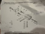
I then removed the draft/ 3pt control valve with the solenoids. I disassembled the spools and they all moved freely and the o rings seemed fine. I did not remove all of the plugs seen in the diagram. I removed and inspected the high pressure select valve (shuttle valve) but did NOTfully disassemble the compensator (unload valve) or check valve. Maybe this was a mistake.

I did remove the solenoids and they were VERY difficult to remove they did not simply slide off. I checked their resistance and they had 4 ohm and they were still magnetized so I put them back on. I verified they would "click" although it didn't seem particularly smooth. Put it all back together and still no lift. There is now some oil dripping from the solenoids when they are manually engaged, but no lift. When the block was off there was oil getting to the bottom of the block but none to the rear hydraulic filter or the 3pt.

I have used a floor jack to ensure the arms will go up on the 3 pt and they are not corroded and they easily lift with a floor jack.
 

Attachments

Russell King

Well-known member
Lifetime Member

Equipment
L185F, Modern Ag Competitor 4’ shredder, Rhino tiller, rear dirt scoop
Jun 17, 2012
8,016
3,155
113
Austin, Texas
That looks like a pretty straightforward hydraulic flow but a complex control system. Being a simple person I would start verifying where the pump actually creates a flow. So I would get to the delivery pipe end opposite the pump and see if you can get it disconnected and see if there is flow out of that pipe. It is part #20 in the first picture in post #5. Take care about the GPM of the pump so you don’t drain the sump. I always try to feed pump output back to the sump through clear tubing so it refills the sump and you can just let the tractor run and evaluate the flow without making a mess. That may be impossible in a cabbed tractor without help. If you have flow there then move to the next place where there should be flow out of a valve.

From looking at the schematics and parts there may be relief valves that can be removed to see if there is flow there. I also note there are some plugs on the cover of the three point cylinder that might allow flow verification to the cylinder itself.

From what I see if the pump is actually known to be working (some other hydraulic system is operating correctly) then the flow is being dumped or diverted somehow or just can’t build pressure due to a bypassing relief valve.

I don’t know anything about the draft system but know it is sometimes the problem with three point hitch operation so if you could verify that it is in a nuetral or off position that should eliminate that.

Good luck.
 

TheOldHokie

Well-known member
Lifetime Member

Equipment
L3901/LA525, G2160/RCK60, G2460/RCK60
Apr 6, 2021
12,971
7,349
113
Myersville, MD
windyridgefarm.us
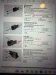
Here are a few more schematics/ part break downs I got from Kubota dealer today. Again any and all help appreciated.
Randomly taking assemblies apart, especially if you do not understand them, is not helpful and potentially creates additional problems.

You have no flow out of the control valve so work backwards along the circuit to see where it dissapears. You need a real hydraulic cIrcuit diagram not a bunch of parts diagrams. Thats not a simple control system - buy a WSM.

Dan
 

Pmschmitt

Member

Equipment
Rtv CPX1140, ZD28
Mar 17, 2019
43
1
8
Navasota, Texas
Relief, compensator, and shuttle high pressure valve all slide easily and no prong damage. Therefore all internals of the 3pt distribution block have been checked but still no. Movement of the 3 pt with manual actuation of the the 3pt solenoid.

I know I have pressure at rear remotes which is the last stop before the 3pt. I disassembled the rear remote distribution block and all o rings seem normal all spools cycle appropriately.

is it possible there is a check valve within the machined casing of the rear tractor between the rear remote block and the 3 pt block? There is none referenced in the WSM.

I have attached some pics of the hydraulic remote block disassembled and where the rear remote block mounts to the tractor casing.

I have also attached a pic of the relief valve that appears to be functioning fine but I will replace the o ring as it is a little smooshed.

again any large M series gurus know if there might be a check valve I'm missing? I'll go get an exploded diagram from Kubota Monday but there is nothing in the WSM
 

Attachments

TheOldHokie

Well-known member
Lifetime Member

Equipment
L3901/LA525, G2160/RCK60, G2460/RCK60
Apr 6, 2021
12,971
7,349
113
Myersville, MD
windyridgefarm.us
Relief, compensator, and shuttle high pressure valve all slide easily and no prong damage. Therefore all internals of the 3pt distribution block have been checked but still no. Movement of the 3 pt with manual actuation of the the 3pt solenoid.

I know I have pressure at rear remotes which is the last stop before the 3pt. I disassembled the rear remote distribution block and all o rings seem normal all spools cycle appropriately.

is it possible there is a check valve within the machined casing of the rear tractor between the rear remote block and the 3 pt block? There is none referenced in the WSM.

I have attached some pics of the hydraulic remote block disassembled and where the rear remote block mounts to the tractor casing.

I have also attached a pic of the relief valve that appears to be functioning fine but I will replace the o ring as it is a little smooshed.

again any large M series gurus know if there might be a check valve I'm missing? I'll go get an exploded diagram from Kubota Monday but there is nothing in the WSM
I popped for a copy if the WSM. I have looked at the hydrauluc circuit schematic and quickly skimmed the description of operation.

Your remotes work so you have pressure and glow coming into the 3pt draft control valve.

I have only skimmed the description but heres my rudimentary understanding. The draft control valve contains two pilot operated proportional flow control valves. When in "neutral" the pump is unloaded to tank through the filter and there is no flow to the draft and position spooos. When a lift operation is commanded the unload circuit/valve is (partially?) closed and flow is sent to the inlets of the draft and position control spools.

If that unloader is not closing there is never any lift pressure present at the position and draft control spools. Manually operating them will do nothing.

Ford used a similar unloading unloading design on their tractors starting with the 1953 NAA and all the way up througjt the 70s or later models. It was a very "simple" hydromechanical system and stuck unloader valves and no lift was a common problem.

The Kubota system is electronically controlled and much more comp I ex. A good handfull of position and load sensors provide input to a microprocessor which then commands various functions in the draft/position control block. My first suspicion is the $2800 controller is out to lunch or a wiring defect is preventing the controller from operating the unloader valve in the 3pt control block.

I suggest you read the description of the 3pt lift controller and trouble shoot ALL of the input and output signals AT THE CONTROLLER HARNESS.

In short, I suspect your problem is electrical.

Dan
 
Last edited:

Pmschmitt

Member

Equipment
Rtv CPX1140, ZD28
Mar 17, 2019
43
1
8
Navasota, Texas
Dan
Thanks for the input. I have replaced the in cab controller as there was a broken wire within the controller.

I will start over on the WSM going through the diagnostics again. I was under the impression the manual over ride would work even if an electrical issue. I was just trying to ensure my issue was only electrical in nature.

Thanks for the input. Honestly going nuts dealing with this thing. I know it has to be something simple I'm just not catching.

I'll circle back and follow up

one other thing your comment stated when bypassed it goes to the rear filter. Well there is no fluid going to that rear filter. When tapped it sounds hollow since I replaced it
 

TheOldHokie

Well-known member
Lifetime Member

Equipment
L3901/LA525, G2160/RCK60, G2460/RCK60
Apr 6, 2021
12,971
7,349
113
Myersville, MD
windyridgefarm.us
Dan
Thanks for the input. I have replaced the in cab controller as there was a broken wire within the controller.

I will start over on the WSM going through the diagnostics again. I was under the impression the manual over ride would work even if an electrical issue. I was just trying to ensure my issue was only electrical in nature.

Thanks for the input. Honestly going nuts dealing with this thing. I know it has to be something simple I'm just not catching.

I'll circle back and follow up

one other thing your comment stated when bypassed it goes to the rear filter. Well there is no fluid going to that rear filter. When tapped it sounds hollow since I replaced it
Icwas under the impression you repIaced the control psnel not the ECU.

I could be wrong but my impression is that filter is the only route to tank for the neutral circuit. If you think there is no oil going to the filter remove it and start the tractor. I suggest you keep your hand on the ignition switch o_O

Dan
 
Last edited:

Pmschmitt

Member

Equipment
Rtv CPX1140, ZD28
Mar 17, 2019
43
1
8
Navasota, Texas
Sorry if my response wasn't clear but the arm rest controller has been replaced and it did clear up the fast flashing 3 pt signal and all of the codes originating from the controller. But it has failed to make the 3pt move at all. I sort of stopped chasing electrical when I couldn't get the valve to manually actuate, but your description makes sense.
 

TheOldHokie

Well-known member
Lifetime Member

Equipment
L3901/LA525, G2160/RCK60, G2460/RCK60
Apr 6, 2021
12,971
7,349
113
Myersville, MD
windyridgefarm.us
Sorry if my response wasn't clear but the arm rest controller has been replaced and it did clear up the fast flashing 3 pt signal and all of the codes originating from the controller. But it has failed to make the 3pt move at all. I sort of stopped chasing electrical when I couldn't get the valve to manually actuate, but your description makes sense.
According to the parts diagrams the armrest controller does not contain the ECU. The ECU is a metal (???) can bolted to the sheetmetal.

Dan 1000006542.jpg
 
Last edited:

TheOldHokie

Well-known member
Lifetime Member

Equipment
L3901/LA525, G2160/RCK60, G2460/RCK60
Apr 6, 2021
12,971
7,349
113
Myersville, MD
windyridgefarm.us
Sorry if my response wasn't clear but the arm rest controller has been replaced and it did clear up the fast flashing 3 pt signal and all of the codes originating from the controller. But it has failed to make the 3pt move at all. I sort of stopped chasing electrical when I couldn't get the valve to manually actuate, but your description makes sense.
I had time to read through the manual a little closer.

The compensator (unloader) valve is a pressure differential shuttle that is shifted by pilot pressure. The pilot pressure is generated when the main lifting spool is shifted to the lift position and incoming oil from the pump is directed to the backside of the shuttle.

Since the main spool is also pilot operated its not clear to me how the manual overide mechanism fits into that picture. The lowering description clearly states the manual over ride operates the pilot spool but not the main spool. The lowering spool also has a circuit thar holds the unloading valve open

Its quite possible your problem is as simple as a sticky unloader shuttle or perhaps something in the lowering spool. I quit reading at that point so how the draft side of the system interplays with position control is still a mystery. But given the basic unloading design I would be scrutinizing that shuttle and the bore in the valve body. It needs ti mive easily.

Dan

1000006546.jpg
 

Pmschmitt

Member

Equipment
Rtv CPX1140, ZD28
Mar 17, 2019
43
1
8
Navasota, Texas
Thanks for Dan. I have disassembled every part of that block inspected and re assembled but maybe I missed something. All spools o rings and springs were intact and moved easily. This includes checking the shuttle valve on the bottom between the spools and the check and compensator valve. I currently have the aux hydraulic block disassembled.

From my reading my understanding was the manual over ride would operate the 3 pt even if electrical issues, but I could be totally wrong.

it would be helpful to understand the touting of the fluid through the rear end casing. I may remove the 3pt controller and blow some air through the passages to see if they go to the filter first or the block