BX1870, No Tach or Hour meter

Boatman

Active member

Equipment
Kubota L2800, Kubota BX1870
Nov 26, 2016
167
54
28
Mill Spring, NC, US
I've done quite a bit of searching on this issue and found a few threads but nothing with the answer to the question I'm going to ask.

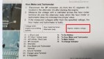
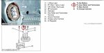
The question. Does anyone know the "proper value" of the signal sent from the alternator to the instrument panel for the tach/hours. I tested as per the WSM and at idle I get ~.482v and that increases as the engine speed increases. I've dug through the manual and have not found the "proper value".


Screenshot (119).jpg


So a bit more info. While mowing last week I noticed the tach/hour stopped registering. Tach does the sweep when powered up. Yesterday when going up a steep hill the engine sputtered and died. Then realized the fuel pump wasn't running. Pulled the mower off and found a wire (red/yellow) going to the fuel pump was broken. Repaired that and the pump is now working again but still no tach/hour. After testing for the "proper value" I ran a jumper wire from the output terminal of the alternator to the input of the of the instrument panel,,,, still no tach/hour. Would really like to nail this down before spending big bucks on a replacement panel.
 
Last edited:

Dave_eng

Well-known member
Lifetime Member

Equipment
M7040, Nuffield 465
Oct 6, 2012
5,123
931
113
Williamstown Ontario Canada
You are not interpreting the page from the WSM correctly.

The required voltage is the battery voltage.

In theory, the tach is using an alternating current pulse internal to the alternator to calculate the rpm's . This signal would not be present on the main alternator output terminal but on one of the small terminals specifically terminal B.

Dave
 

Attachments

Last edited:

Boatman

Active member

Equipment
Kubota L2800, Kubota BX1870
Nov 26, 2016
167
54
28
Mill Spring, NC, US
You are not interpreting the page from the WSM correctly.

The required voltage is the battery voltage.

In theory, the tach is using an alternating current pulse internal to the alternator to calculate the rpm's . This signal would not be present on the main alternator output terminal but on one of the small terminals specifically terminal B.

Dave
Thanks for the reply. I had a hunch I was looking for battery voltage but needed a confirmation. I did check from the B post. Im going to double check my finding later today.
So it looks like if I get the same results it looks like I may have alternator issues. Wonder if the broken wire I found grounded and shorted the alternator module?

Any way you know of to send a signal to the tach to confirm its okay?
 

Dave_eng

Well-known member
Lifetime Member

Equipment
M7040, Nuffield 465
Oct 6, 2012
5,123
931
113
Williamstown Ontario Canada
Thanks for the reply. I had a hunch I was looking for battery voltage but needed a confirmation. I did check from the B post. Im going to double check my finding later today.
So it looks like if I get the same results it looks like I may have alternator issues. Wonder if the broken wire I found grounded and shorted the alternator module?

Any way you know of to send a signal to the tach to confirm its okay?
If the alternator is charging properly, it is unlikely it was damaged. The tach signal comes from the diode bridge which would be tough compared to some of the electronics in the internal regulator.

I do not know a way to send a signal to the tach. I am certain there is one but finding out what it is for different rpm's would need a conversation with the original designer. Further, generating a varying frequency signal would require specialized test equipment.

Dave
 

Boatman

Active member

Equipment
Kubota L2800, Kubota BX1870
Nov 26, 2016
167
54
28
Mill Spring, NC, US
If the alternator is charging properly, it is unlikely it was damaged. The tach signal comes from the diode bridge which would be tough compared to some of the electronics in the internal regulator.

I do not know a way to send a signal to the tach. I am certain there is one but finding out what it is for different rpm's would need a conversation with the original designer. Further, generating a varying frequency signal would require specialized test equipment.

Dave

I double checked my previous findings and it's the same result. ~.48 v between terminal B to ground.

I assumed the alternator itself is charging fine because no light came on, but now I'm questioning that assumption. I did do the check for the indicator light and that test showed the light does work.


I guess tomorrow I'll test the charging output of the alternator.
 

Boatman

Active member

Equipment
Kubota L2800, Kubota BX1870
Nov 26, 2016
167
54
28
Mill Spring, NC, US
So an update.... I pulled the alternator and had it tested at rebuild shop Working perfectly. I questioned the reading I was getting from the tach output and he explained that it was correct. Output signal to the tach can't be battery voltage. He even pulled another alternator off the shelf, spun it up and got the same results.


He feels I have another broken wire someplace.
 

wgator

Active member

Equipment
L4701HST, FEL and other stuff.
Jul 28, 2018
482
147
43
NC
So an update.... I pulled the alternator and had it tested at rebuild shop Working perfectly. I questioned the reading I was getting from the tach output and he explained that it was correct. Output signal to the tach can't be battery voltage. He even pulled another alternator off the shelf, spun it up and got the same results.


He feels I have another broken wire someplace.

Read test step 3 carefully. You have a different reading than battery voltage so it means your tach and hour meter are bad.
 

Roadworthy

Well-known member
Lifetime Member

Equipment
L2501 HST
Aug 17, 2019
1,649
525
113
Benton City, WA
I keep seeing reference to the alternator output terminal for the tach. It appears a dc voltage check is being made. I suspect if one were to look at it with an oscilloscope one would find it's a string of pulses or pulsating dc which the tach "counts" to give rpm. As the engine speeds up more pulses indicate higher rpm. If the pulses make it to the back of the tach and it can't count them the instrument itself is bad. If the pulses don't make it you need to determine where you're losing them.
 

Boatman

Active member

Equipment
Kubota L2800, Kubota BX1870
Nov 26, 2016
167
54
28
Mill Spring, NC, US
Okay,,, final update. All is working well. No need for a new instrument panel. The issue was as the alternator guy said,,, "you have a broken wire somewhere". As it turns out there are two wires on the positive side of the fuel pump. I found one of them broken last week and that fixed the fuel pump running. I did not notice that the other wire was also broken. The wire inside the jacket was broken. A swift tug today and the jacket broke. Repaired that wire and Voila!!!, tach/hour are working again. It looks like the key switch sends power to the fuel pump through the first wire that was broken. The second wire then continues on to the center terminal of the alternator plug to "turn on the alternator". Without that wire I had no charging or tach/hour.

Also what I figured out is that you cannot test the tach output of the alternator with it unplugged as the WSM states. The voltage you get is just stray voltage at ~0.4v. With the alternator plugged in you can test the tach output at #4 terminal of the instrument panel plug. That tests as ~7.4VDC (not AC). Half of the battery voltage. Roadworthy you are correct about using an oscilloscope to measure the pulses.