Grey market FEL on L1-24 Sunshine

Crazy Horse

New member

Equipment
L2950
Oct 16, 2016
67
0
0
Graham Wa U.S.A.
Ok, forget the drawing.
I took the line going to the rear end off, it was the line tied into the tee. I capped the tee.
I started the loader, everything functioned perfectly, the loader worked perfectly. I started messing with the electronic controls on the fender, and now the loader doesn't respond at all. Hopefully I didn't create an internal breakdown. I will fiddle with those electronics some more, as I think that's how I lost the loader function. Will let you know what shakes out.
It looks like the fel control valve has a power beyond built in, as the line coming off of the control valve goes to the fitting with those 2 bolts in it.
The line coming off of the tee went to that fitting on the rear end. That line is now removed.
 
Last edited:

torch

Well-known member

Equipment
B7100HSD, B2789, B2550, B4672, 48" cultivator, homemade FEL and Cab
Jun 10, 2016
2,593
836
113
Muskoka, Ont.
No, on kubota's they are an open loop system, all fluid flows thru the pressure relief valves not around them,
I beg to differ. This is from the B7100 WSM:


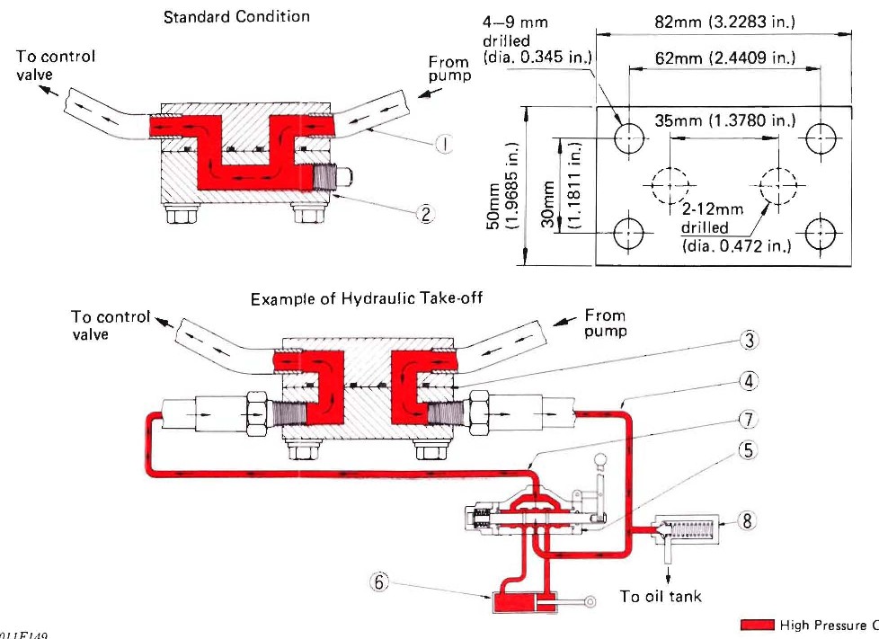
Note the pressure relief valve location -- #8, between the supply from the pump and discharging into the tank. Fluid flows continuously through the open centre spool valve, but no fluid flows through the relief valve unless the pressure exceeds the relief valve setting.

Similarly, please study this page from the L3540 WSM:


Again, the relief valve is between the pump outlet and the tank inlet.

The difference between a closed centre system and an open centre system is that the closed centre system maintains maximum pressure in the lines to the control valve at all times -- the oil does not circulate through the system when the control valve is in neutral because the closed spool centre blocks the flow.

Conversely, an open centre system has variable pressure in the lines. When the control is in neutral the oil flows through the open centre to the tank. When the control is operated, the centre is closed as the spool diverts the oil flow to the selected cylinder port, and line pressures rise as the cylinder meets resistance. When the cylinder reaches the end of it's travel, the system is effectively dead-headed -- the fluid has no place to go.

The pressure would continue to climb until something burst, except for the presence of the relief valve. When the pressure reaches the set-point of the relief valve, it overcomes the resistance of the relief valve spring and the pressure is kept within the safe limits by bleeding fluid to the tank.

Piping a relief valve in the middle of the tank return line not only provides no protection for the cylinders, it would serve to restrict the flow from the spool valves to the tank, as fluid would have to overcome the relief valve spring pressure to allow any flow.

Ok, now how does this apply to the problem at hand?

The force that can be applied by a cylinder is equal to the fluid pressure times the surface area of the piston. But the two ends of the cylinders have two different effective piston areas, because one side of the piston is connected to the rod. No fluid can push on the area covered by the rod connection. So, for a given fluid pressure, the cylinder will have more extension force than retraction force. Similarly, it takes more fluid to fully extend the cylinder than it takes to retract the cylinder.

Finally, for a double-acting cylinder to move, fluid must return to the tank from the opposite side of the cylinder. If the fluid return is restricted, the cylinder will be fighting itself. Under that condition, extending the cylinder will go faster than retracting the cylinder because of the difference in area (and therefore force applied) between the two sides of the piston. When retracting the cylinder, there's a double whammy: not only does the smaller area have to overcome greater force, but at the same time it must return a greater quantity of fluid to the tank!

The configuration on Crazy Horse's machine is typical: extending the boom cylinders raises the boom. Extending the bucket cylinders dumps the bucket. He indicates that both those actions seem to work comparatively well. But actions requiring cylinder retraction -- lowering the boom or curling the bucket up -- are very slow.

If you are correct that there is a relief valve installed inline between the control and the tank (and I see no reason to question it), then I believe that would fully explain his symptoms, because returning fluid would be restricted by the relief valve spring pressure.

EDIT: I just saw Crazy Horse's sketch. If the "rear end" fitting is a relief valve, then it's not in-line. It's exactly where it's supposed to be. Likely the setting is just too low. Capping that off is a BAD IDEA -- it's the safety that protects the rest of the system
!!!
 
Last edited:

Crazy Horse

New member

Equipment
L2950
Oct 16, 2016
67
0
0
Graham Wa U.S.A.
I did remove that line and capped it. The loader functioned perfectly, like it should. Then I left the tractor running for about five minutes, tried running the bucket again and it basically had lost function. Now I did fiddle with the electronic controls to see if I could get the 3 point to function properly, which I couldn't, which is to me a lesser issue, my priority is getting the loader to work.
So here's what may be the thing, if it has the system torch described, then removing that line would cause it to build up a ton of pressure, rendering it inoperable, as it's under a ton of pressure with no release.
One final thing: the pump did get extremely hot while that line was capped.
 

Crazy Horse

New member

Equipment
L2950
Oct 16, 2016
67
0
0
Graham Wa U.S.A.
Can you give me any insight on setting the relief valve properly? I will go ahead and reinstall that line tomorrow.
Also, I didn't realize what causes to cylinder to retract is that oil is directed to the opposite end of the cylinder I never gave that much thought, assumed it was the weight of the boom, and or the pressure simple being released from the other side. Which doesn't stand to reason now that I know.
So, which route does the oil take back to the reservoir? Right now if it isn't the line that goes to the 3 point, which to me needs to have the same pressure as does to fel to operate, making it a pressurized line then there is no relief line, that would be the aforementioned 7th line on the valve. There is none.
Now, I'm not well versed in hydraulics, so I may be missing something but if there is no relief line from the control valve to the reservoir for the displaced oil to go isn't it being forced somewhere, like against the pump itself, and then against the release valve? This doesn't seem right to me, sounds like we are missing a line.
Again, I'm not well versed in hydraulics, so if there's an obvious error in my theory let me know.
 
Last edited:

torch

Well-known member

Equipment
B7100HSD, B2789, B2550, B4672, 48" cultivator, homemade FEL and Cab
Jun 10, 2016
2,593
836
113
Muskoka, Ont.
Can you give me any insight on setting the relief valve properly?
On an adjustable relief valve, there is a screw adjustment of some kind -- quite possibly under a dust cover.

So, which route does the oil take back to the reservoir? Right now if it isn't the line that goes to the 3 point, which to me needs to have the same pressure as does to fel to operate, making it a pressurized line then there is no relief line, that would be the aforementioned 7th line on the valve. There is none.
The 3ph control is also an open centre type spool valve. Unless the control is directing fluid into the 3ph lift cylinder(s) then the oil going into the control is passing through into the tank.

If your FEL control does NOT have the Power Beyond feature, then all fluid exhausting from the cylinders and all fluid passing through the spool valve centre is directed out a single discharge port. If that port is connected to the 3ph, then it passes through the 3ph open centre and into the tank.

If your FEL control DOES have the Power Beyond feature, then all fluid exhausting from the cylinders is directed to the tank via a third line between the Tank port and the tank. But all fluid passing through the spool valve centre is directed to the downstream function (in this case, the 3ph) through the PB port.

I am surprised the FEL control valve does not incorporate an integral relief valve, like the Kubota control or most aftermarket valves. If it does have a built-in relief valve, then the relief valve discharge should be directed to whichever port goes to the tank.
 

torch

Well-known member

Equipment
B7100HSD, B2789, B2550, B4672, 48" cultivator, homemade FEL and Cab
Jun 10, 2016
2,593
836
113
Muskoka, Ont.
In your pictures of the cylinders, there's a valve handle near the top of the starboard boom lift cylinder. Where is that piped to? Is it a manual lowering valve, a flow restrictor or ???
 

Crazy Horse

New member

Equipment
L2950
Oct 16, 2016
67
0
0
Graham Wa U.S.A.
There is no Manuel neutral setting on the 3ph, it's just your standard control you pull up or down, it does not automatically return to a default position.
 

torch

Well-known member

Equipment
B7100HSD, B2789, B2550, B4672, 48" cultivator, homemade FEL and Cab
Jun 10, 2016
2,593
836
113
Muskoka, Ont.
There is no Manuel neutral setting on the 3ph, it's just your standard control you pull up or down, it does not automatically return to a default position.
The 3ph is different -- it's a single acting cylinder (no power down). The control applies fluid to the cylinder to make it go up, and dumps fluid to the tank to lower the hitch by gravity only. The control should have a centre position where the 3ph stays put.
 

Piker

Member

Equipment
2012 Kubota 2320, 2002 Honda Rubicon
Dec 1, 2010
164
0
11
Riverview, NB, Canada
Any progress on this problem? Worked in electronics for 38 yrs. but the hydraulics on these tractors bamboozle me to death. Can't wait to see the solution. I have a 2012 B2320 HST with FEL & P/S - may it continue to work as flawlessly as it does now.
 

Crazy Horse

New member

Equipment
L2950
Oct 16, 2016
67
0
0
Graham Wa U.S.A.
Yea we did get the fel to work, though I don't know what exactly got it working. We took the rear end apart, put new gaskets into the 3ph control valve and put everything back together and it worked. I hired a buddy better versed in hydraulics than me to work on it, I do think he got it to work before he took the rear end apart, but we did not get the 3 ph to work at all.