B7100 cam plug low oil pressure and dynamo bearing replacement

D2Cat

Well-known member
Lifetime Member

Equipment
L305DT, B7100HST, TG1860, TG1860D, L4240
Mar 27, 2014
13,007
4,389
113
40 miles south of Kansas City
"Does not seem to be much of the splines left on the front crankshaft. Almost looks like they have been stripped. I'll have to look to see if there is anywhere it could have been rubbing:"

Tractor probably had a pump or other attachment at one time, requiring power from the crankshaft, causing the worn splines.
 

chickenfriend

Member
Jul 2, 2016
44
4
8
FR, VA
From the diagram in the parts manual, looks like there is supposed to be a cover for the shaft stub held on by one bolt. Missing this, but the area is pretty well shielded from operator contact so I am going to leave it alone.

Added a few more part numbers to the earlier parts of the post.

Still waiting on the pivot pin.

I was wondering if the pivot pin could be center drilled, with two side holes as outlets for the grease, under the collar, and a grease fitting on each end? You would have to make sure the outlet holes for the grease would not be located at the O-rings riding on the pin. Just a thought.
 
Last edited:

chickenfriend

Member
Jul 2, 2016
44
4
8
FR, VA
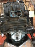
All the engine and dynamo work is completed and after running the old oil and filter for about 15 minutes, I changed it all out to new.

However, I have a 
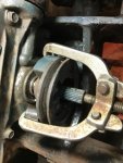
major problem: in while attempting to drive in the new front bushing on the front axle for the new pivot pin, I noticed that the top of the bore in the casting is cracked, up to the backstop land on the inside of the bore; in other words, what would be the length of the bushing.

It is possible this is my fault, since I think it would have been better to have pulled the bushing in with a long threaded rod with a nut and washers, than try to pound it in with a hammer. I don't think I was hitting it exactly square because of the tie rod being a little in the way.

The bushing and the bore is a very tight fit, as I recall from trying to remove them with a punch. Maybe just a little bit too tight?

My plan is use some nickel alloy cast iron welding rod and fix it. With the edge of a grinding wheel on my hand grinder, I will groove-out the crack from the top about half way down the thickness of the casting.

I am concerned primarily with getting a good structural repair. The area is not under any oil pressure. The bore just needs to hold the bushing and give a decent seal on the inside for the pivot pin.


Update: I have thought about this for a couple hours and have a plan!

I have concluded that Kubota's interference on the pivot pin bushings-to-housing bore is insanely too much. They fit so tightly that an outer o-ring should not even be necessary!

I am still going to weld up the crack, but I am not going to worry about penetrating all the way to bore with the weld; I just want to make the housing strong and stop the crack. I don't have a way to re-machine the bore if I welded down to the inside.

After the welding, I will clearance both bores with a sandpaper flap wheel so that the bushing will tap in, not have to be beaten in. For the cracked bore, I'll remove the outer o-ring on the bushing and use seal retainer anaerobic sealant to set it on the bore. That way, there will be no way oil can seep out the crack from the inside.

For the other bushing, I'll clearance the bore, too, for less of an interference fit. However, I'll install it normally, keeping the outer o-ring.

Result:

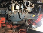
I cut out a groove in the axle housing with a metal cutting wheel on my hand grinder. From the inside of the housing bore, I could see that the crack ended at the backstop for the bushing, so on the outside of the housing, I went back that far with the groove. At the bore entrance, I went deeper with the groove, nearly all the way through.

This shows the beginning of the groove. I went down to the bore, in the front, to get complete penetration there:


After blocking the rears of the bores with a round washer with the center taped, I used a Dremel sandpaper flap wheel to add clearance to the bore. I did a few test installs with one of the old bushings. I wanted it to tap in with the mallet, not beat in.

Welding finished:


After cleaning everything up with brake cleaner, and grinding the weld on the housing smooth, I installed the front bushing with Permatex anaerobic sleeve retainer, without the outer o-ring installed.

I installed the rear bushing normally. Lubed both the insides of the bushings and the pivot pin with moly grease.

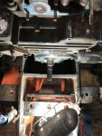
One thing to remember is that the plate steel carriage must go on the axle first; otherwise, the oil pan will be in the way of inserting the pivot bolt if you try to mount the carriage on the block.

So that is about it. All these problems started by a tiny, missing oil galley plug.

One more thing, I noticed that when the oil filter is removed, the oil dribbles into the flat area of the carriage underneath the crankshaft pulley. There was a ton of gook there when I first pulled it off, now I know where it came from. The area does not clean itself. I'll have to put a piece of sheet metal under the filter next time I change it.

Copper washer on the oil plug is M12.
 
Last edited:

Jimc3165

Member

Equipment
1982 B7100 HST-D
Jul 22, 2015
130
0
16
CLEVELAND, GA
chickenfriend, I have used your post so far with the repair on my B7100 and it has been very helpful. 1 difference I have found so far is my Crankshaft pulley is a little different than yours. The nut size was the same 1 1/8 but the pulley had 3 holes in it and I thought I had a puller that would use the bolts that came out of it to remove it. I thought wrong, but there is more than 1 way to skin a cat. I used a 3 jaw puller and 2 small 1/4 inch scokets to make all 3 legs the same and it worked just as well as it would have with the correct puller. Thanks again for the write up it has been very helpful.
 

Attachments

chickenfriend

Member
Jul 2, 2016
44
4
8
FR, VA
chickenfriend, I have used your post so far with the repair on my B7100 and it has been very helpful. 1 difference I have found so far is my Crankshaft pulley is a little different than yours. The nut size was the same 1 1/8 but the pulley had 3 holes in it and I thought I had a puller that would use the bolts that came out of it to remove it. I thought wrong, but there is more than 1 way to skin a cat. I used a 3 jaw puller and 2 small 1/4 inch scokets to make all 3 legs the same and it worked just as well as it would have with the correct puller. Thanks again for the write up it has been very helpful.

That was a smart invention, and the picture of what you did was priceless. I'll remember your trick should I ever run into a similar situation.

I am glad you found my thread helpful and good luck to you.

I am glad you bumped this. I always like to "clean up" my posts after I have forgotten about them for a while, to make sure they make sense!
 
Last edited:

Jimc3165

Member

Equipment
1982 B7100 HST-D
Jul 22, 2015
130
0
16
CLEVELAND, GA
I appreciate the comments because I have another question. Attached are 3 pics the 1st is a straight down shot and it seems obvious that the gear cover is not going to clear the frame. The second is a straight on shot and the third is of the side of the frame. You spoke of dropping the front axle so that the cover would clear the frame but I'm not clear on what you did. In the third pic there are 8 bolts on the side of the engine is that the piece that you mentioned that was bolted on for weights? If I drop the axle and take all 16 of those out will that frame piece move forward so The I can clear the end of the crankshaft?

On a side note the 3 jaw puller only worked because the pulley was a cast metal unit, I have tried it on an automotive pulley before and had to buy a new one. I tried to tap the pulley like you did but mine wouldn't move hence the puller. :)
 

Attachments

chickenfriend

Member
Jul 2, 2016
44
4
8
FR, VA
In the third pic there are 8 bolts on the side of the engine is that the piece that you mentioned that was bolted on for weights? If I drop the axle and take all 16 of those out will that frame piece move forward so The I can clear the end of the crankshaft?
Yes. You will have to take out all of those bolts. With the floor jack under the engine, you will be able to control the brace bars as they separate. Be careful that the front axle does not go squirrelly on you--chock the front wheel or brace the axle some other way. It is also possible that the round protection tube for the PTO, where you see that rubber boot clamp, may pull loose from the pipe as you separate the brace from the tractor, but it is just a cover and can be re-inserted into the boot without any trouble. Steady as she goes!
 
Last edited:

Jimc3165

Member

Equipment
1982 B7100 HST-D
Jul 22, 2015
130
0
16
CLEVELAND, GA
OK some more comments on this, since I am just now getting mine back together with instrumentation so I can monitor the oil pressure and water temp. A pair of 90 degree needle nose pliers was indispensable for putting on those pesky hidden nuts. My new dynamo did not have a cutout for that gear case bolt and since I was following the sequence of reassembly in this thread I did not realize that that bolt is impossible to access with out the cutout in the dynamo so if you are installing a new dynamo you have to install the gear case cover first. The nut behind the dynamo is not that hard if you use a 90 needle nose to hang the washer and start the nut just a half of thread and if you lubricate the stud first then hang the nut you can stick your finger in there and turn the nut to run it down so you don't have to spend an hour with the ratcheting box end wrench turning the nut 1 click at a time. Oh also you must do as Chickenfriend suggested for the gear case gasket because it is a bear to get on correctly so minimal gasket sealer was suggested and I did not follow those suggestions and ended up buying a second gasket because I messed up the first one.
 

chickenfriend

Member
Jul 2, 2016
44
4
8
FR, VA
Hello folks. Been over a year. Just updated the picture links, switching from Photobucket to Imgur, for the pic host.

I also added a few more pictures and did some other editing.

Here are a few final shots of the tractor back together, with painted wheels and new tires. I used Allis Chalmers Orange on the wheels and Carlise trencher tires (maximum plies) which I was able to hand mount.


Last edited:

JohnDB

Active member

Equipment
M4500DT
Jun 9, 2018
376
63
28
NZ
Nice looking job!

I was puzzled about the heavy interference fit that the front axle pivot bush had, that might have lead to the cracked housing. Normally (in my experience anyway) with such heavy interference fits the manufacturer specifies shrinking the bush by soaking it for a while in liquid nitrogen or packing it in dry ice. It's amazing how much steel shrinks when it gets cold. I've seen liquid nitrogen used for installing solid steel king-pins for Mercedes buses. It shrunk enough that it literally dropped into place with no force, and then locked solid in the axle when it warmed up. Anyway, could be something to try another time.

Has anyone seen the WSM for one of these tractors - what does it say about fitting that bush?